| < Previous page | Next page > |
|
Form coordinates from section data
In this exercise you will learn how to
Why Do You Need to Learn This?
When points are picked up with a Level and tape, you bring back Chainage, Offset and Height which is all the values you need to draw Profiles and Sections.
However, since you do not have east or north coordinates, you cannot draw a plan, or contour the points.
Here we will show you how to calculate coordinates for this type of data, so that when all your electronic equipment is off on a major project, and your best client phones up with an urgent need to get out a contour plan of a small length of road, you will be able to dust off the automatic level and help her.
Before you can carry out these calculations, you must know the Alignment that these sections are meant to follow.
This is usually defined by a centreline, but can also be a control line offset from the centreline, as long as the offset is constant.
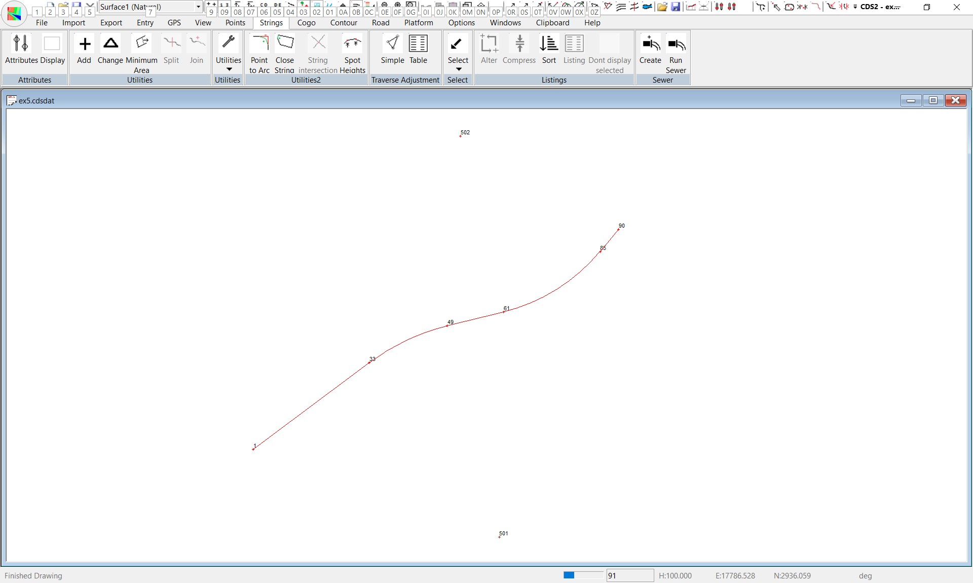
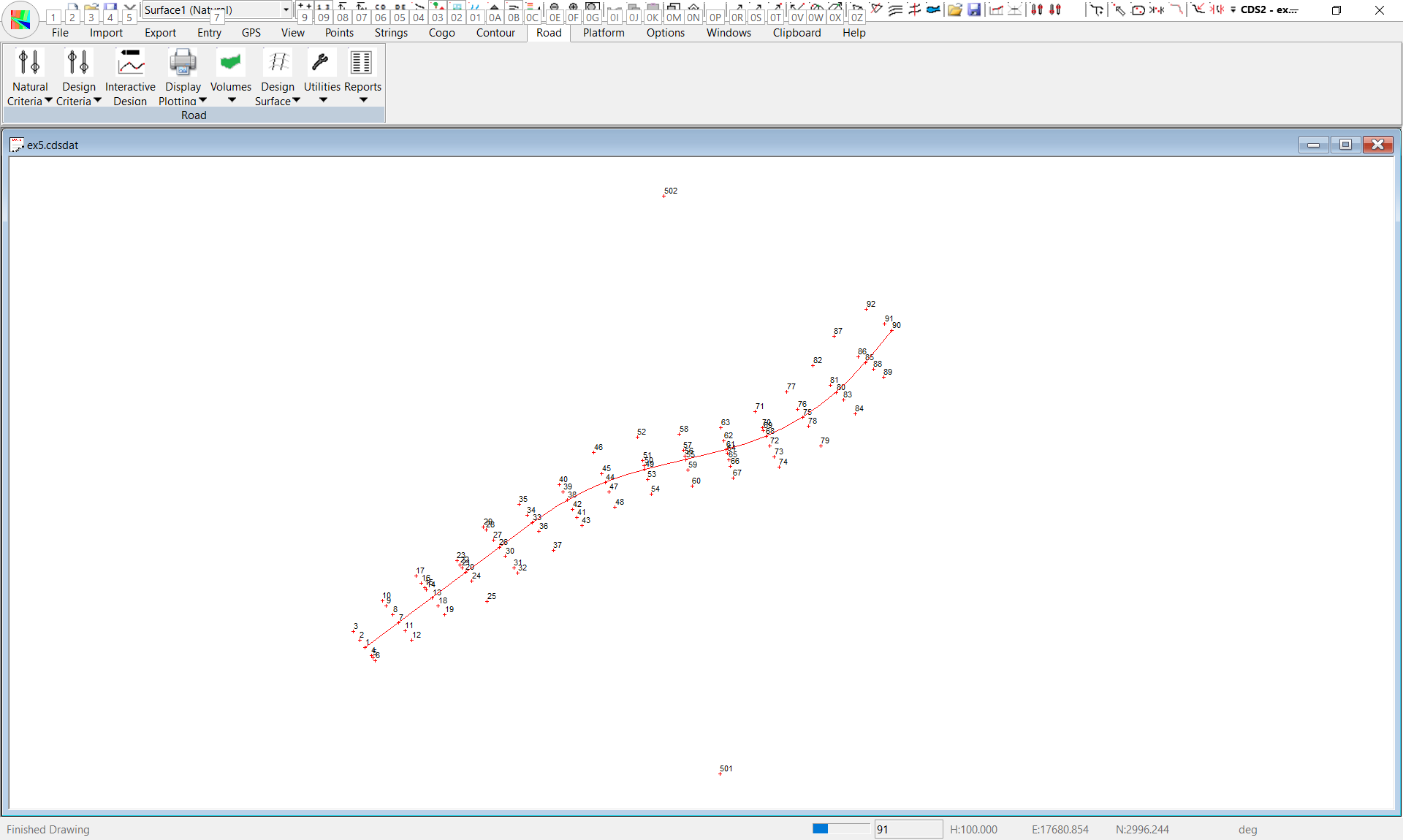
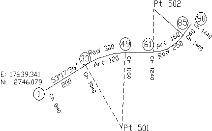
The drawing on top of the next page shows you the alignment of the data collected and used in Tutorial 5.
You should Start CDS and Open Job EX5 in the Foresoft\cds2\tutor folder.
Close the Job that was previously open, and Maximise the screen.
Do not be alarmed if the screen is blank, because if you remember from Tutorial 5, we had no coordinates, and without coordinates, the program has nothing to display on this screen.
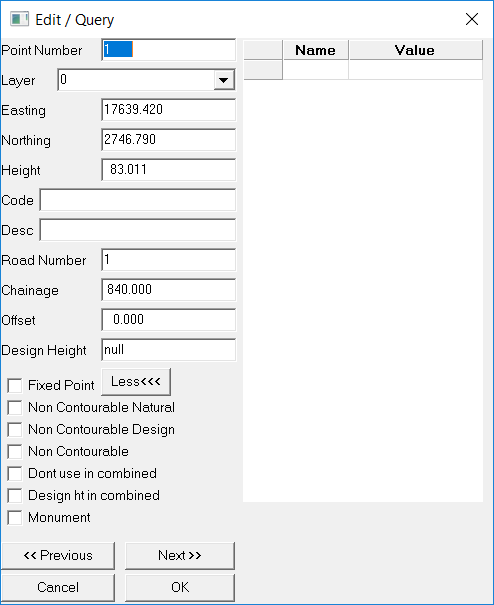
Now the first thing to do is to enter the given coordinates of Point 1, which is the centreline point on our first section.
Add a Known Coordinate
Now select OK.
You will be asked if you wish to save the changes, and you should select Yes.
Having established a coordinate for the starting point of the alignment we will now use the calculation routines to calculate the remaining points.
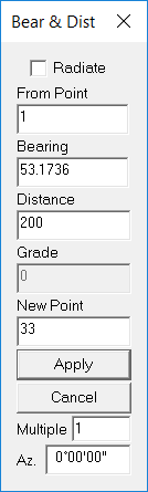
Calculate with Bearing and Distance
Pull down the Cogo menu and select Bearing and Distance
The from Point is 1 and the Bearing is 53.1736.
Enter the distance of 200, and then position the cursor in the field which says New Point.
Now Cancel the Bearing and distance routine.
Arc & Chord Calcs
Pull down Cogo and highlight Curves, and then select Arc/Chord calculations.
The centre Point is 501, and the start point on the radius is 33
Leave “Absolute” and “Arc” selected and the clockwise button checked.
The Arc length is 120, and the new point is number 49.
When you apply this you will again be told that the point exists, so again select the Recalculate option.
Now Zoom Extents to get a view of the whole job.
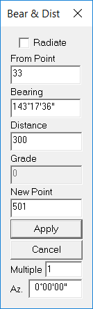
Next you need to pull down Cogo, and select Bearing and Distance again.
From point is 49.
Position the cursor in the bearing field.
You are not shown expressly what the bearing you need is, but you have sufficient information to arrive at it as follows.
The bearing you need is at right angles to the line between Points 501 and 49.
Press the “P” key, click on point 501, followed by 49, and you will see the bearing between those two points appear. Press the “R” key and you will see the bearing alter by 90° to 76° 12’ 42”.
Note, if you are not pointing to the points, you can type in 501,49 and then press the Tab or Enter key to get the original bearing. Then move the cursor back up into the Bearing field and press R.
The Distance is 80 and the new Point number is 61, and when you apply, you can again recalculate.
Next position your cursor in the bearing field, and this time press the “L” key to take 90 from the bearing shown. Enter a Distance of 250 and a Point Number of 502 and apply.
Next close bearing and distance, pull down Cogo and highlight Curves and select Arc/Chord.
The centre point is 502, the start point is 61, and you must make sure that the Anti-Clockwise button is selected. The Arc length is 160 and the new point is 85 which you will need to recalculate.
Next do another Bearing and Distance calculation from 85.
Use ‘P’ in the bearing field to specify the bearing between Points 85 and 502, and press ’R’’ to add 90 to this value. Enter a distance of 40 to a new point number of 90 which you will need to recalculate.
Now you have finished the calculation of all the alignment points it is time to define the alignment string.
Adding the Alignment String
Pull down the Strings Menu and select Add.
Pull down the folder field and select “lots” which is the only folder offered.
Enter an ID of “cl”, and then define the string s 1,33,+501,49,61,-502,85,90.
Calculate Coordinates from Chainage & Offset
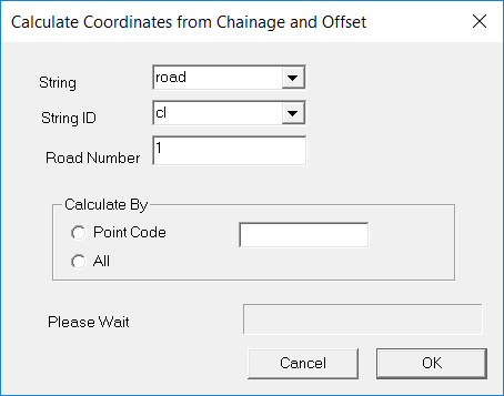
Pull down the Road -> Utilities -> Calculate Coordinates from Chainage and Offset. The screen will now appear as below.
Pull down the Folder field and select ‘Lots” Now pull down the ID field, and select CL
Select All points to be calculated. Then select OK
Once the calculation is complete, you should see a screen similar to that shown on the below.
(If as sometimes happens, it doesn’t appear exactly like it is supposed to, don’t panic - simply do a Zoom Extents and all should be well.)
Form the Contours
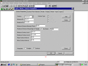
Now, since we set out to prove that we could get a contour plan of points which you picked up with a dumpy level in cross section format, you should pull down the Contour menu and select Surface Parameters to see the screen below.
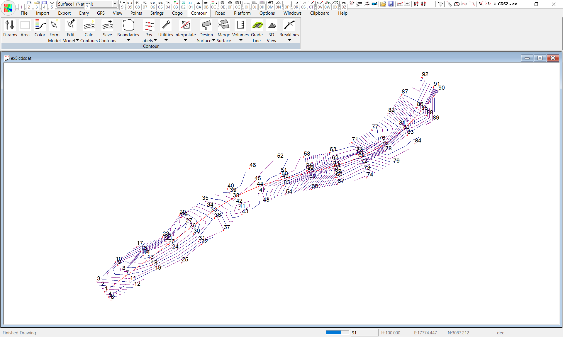
Since you have a couple of concave areas, it is wise to limit the maximum triangle side to prevent the formation of unwanted contours, so set a value of 90 metres. Next form the model, and then calculate contours to achieve the screen above.
|