| < Previous page | Next page > |
|
Forming a platform for bulk earthworks
In this Tutorial you will learn
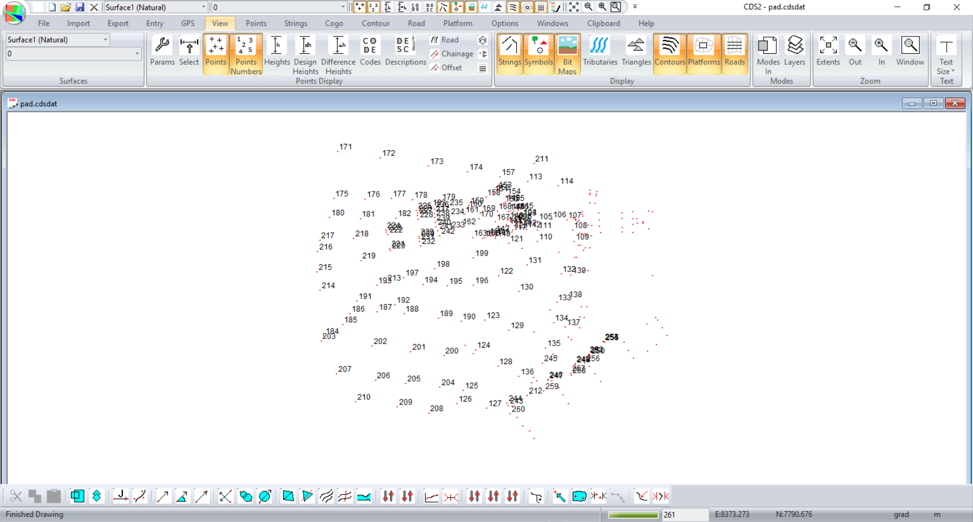
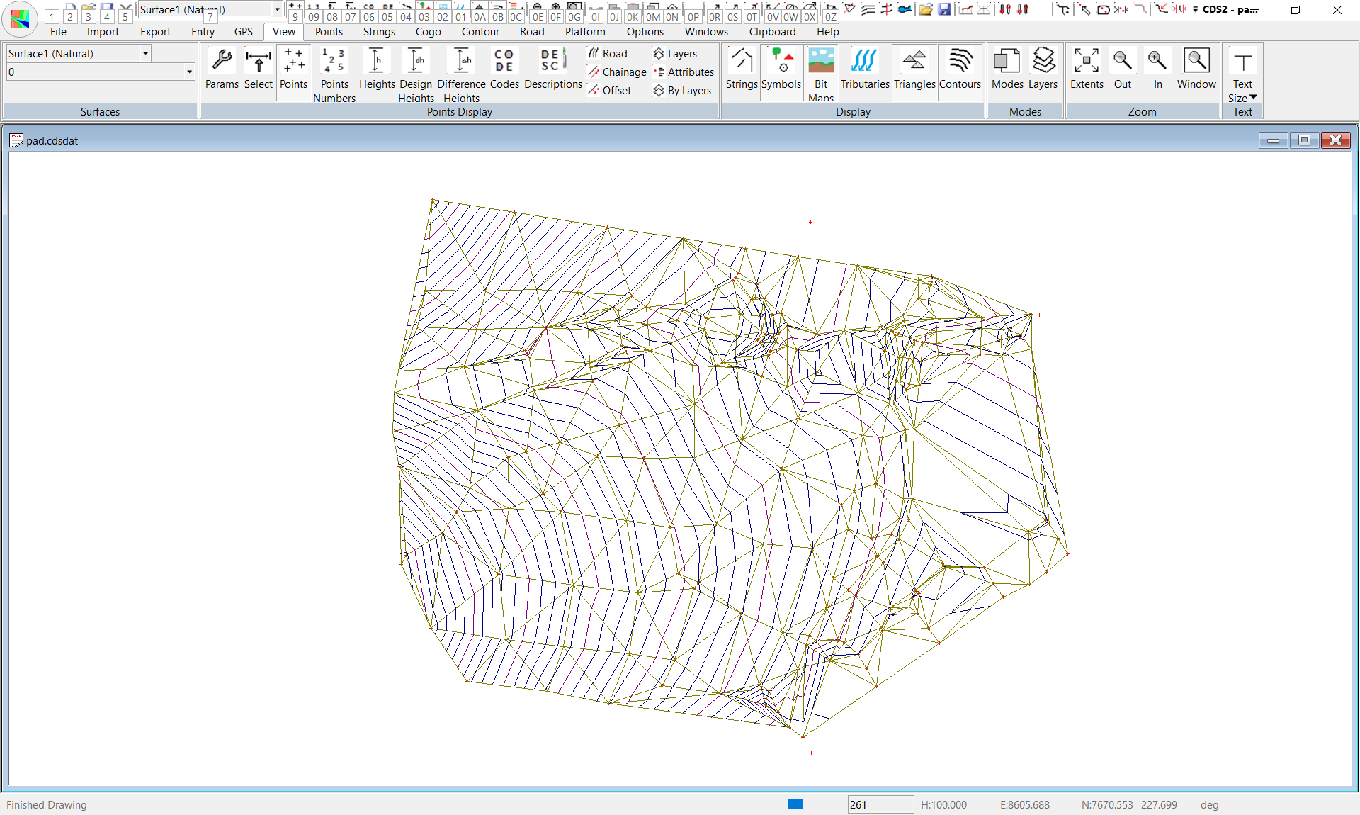
Base data has been supplied in a Job with an ID of "PAD" Start CDS and use File Open to open "pad.cdsdat" located in the my documents\foresoft\cds4 tutor folder. The screen should appear as seen below.
Pull down the Points menu and select Add Points - you will notice that your cursor changes to a cross.
Position it somewhere on the model and select a point.
When the Add/Edit/Query box appears, enter a Point Number of 500, and Easting of 8690, Northing of 7540 and a Design Height of 225.
Select OK, and Point 500 will appear on the screen.
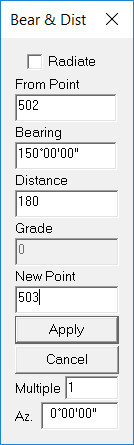
Now pull down the Points menu and turn Add Points Off (or press the Escape key to achieve the same ‘off switch’) and the cursor will revert to the normal pointing arrow. Next pull down the Cogo menu and select Calculate by Bearing and Distance to see the screen below right
I suggest that you define pads in a String Folder with a name of "PAD". This way we logically group the pads together; gthough it is not necessary.
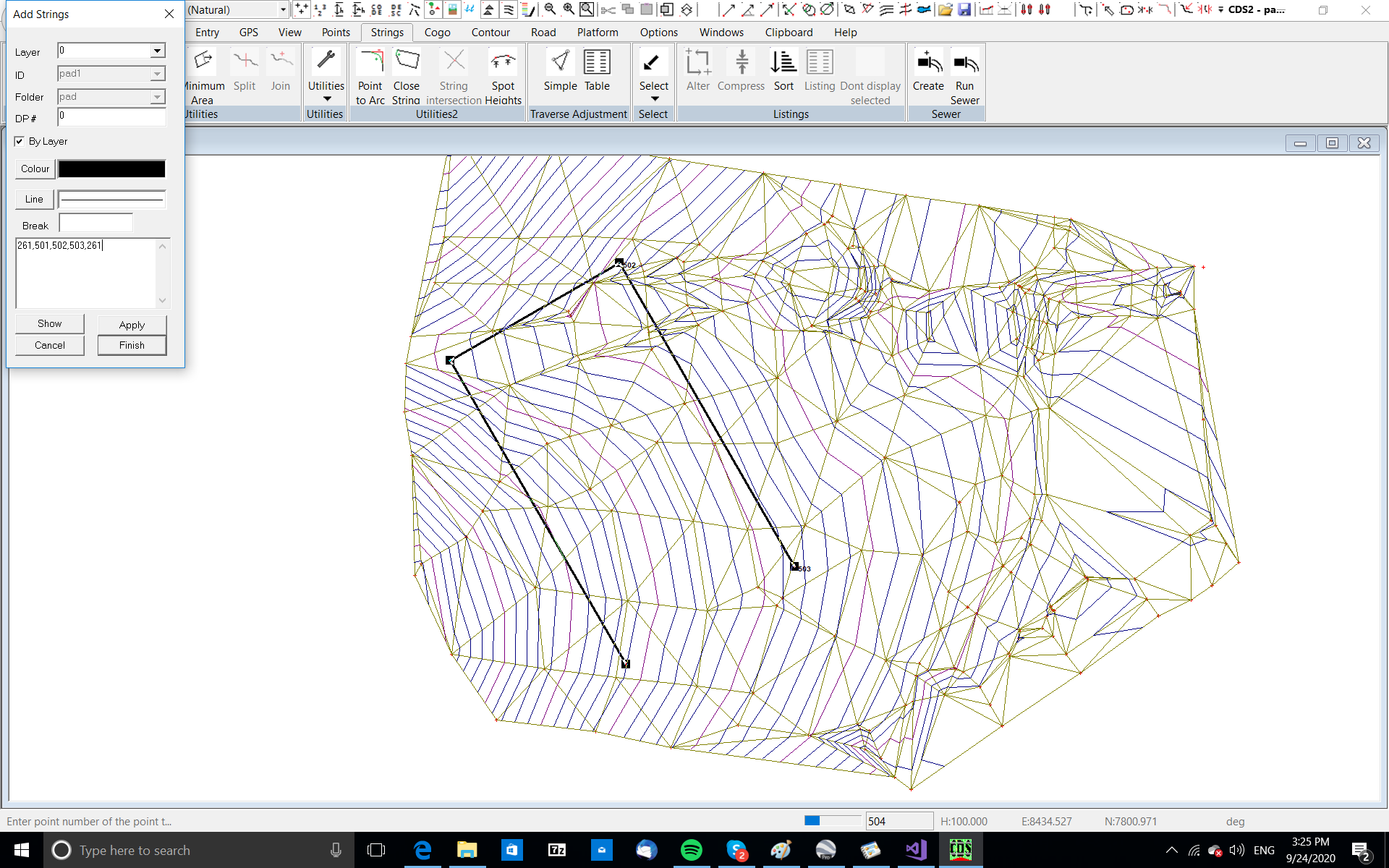
Pull down the Strings Menu and select Add.
Drag the Strings box down to the bottom right hand corner so it is clear of the area where the pad is located
Type in ‘pad’ for the folder name.
Note that it doesn’t matter whether you try and use upper case or lower case, the program will convert everything to lower case as you enter the Folder name. This is necessary to avoid some slight confusion between file or folder naming conventions in different version of Windows. Use an ID of P1 and accept the default pen and linetype.
Move the cursor into the string entry field, and either type in the string 500,501,502,503,500, or use your mouse to select the points.
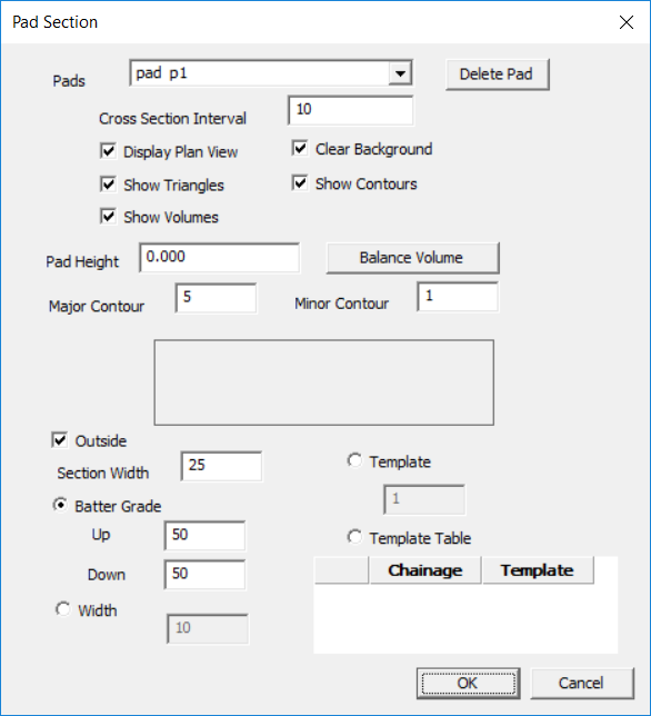
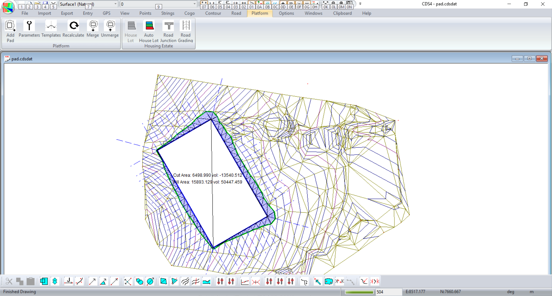
CDS will now show us the Platform design as we go. We can change parameters and see the result straight away. The first thing I suggest is to guess an initial start height. I have added a value in of 225 and click OK. At the end of the process your screen should be similar to the one shown above.
The idea is to iteratively change the values and look on the screen at how it looks. The pad knows how to display itself and nothing is added to the database yet.
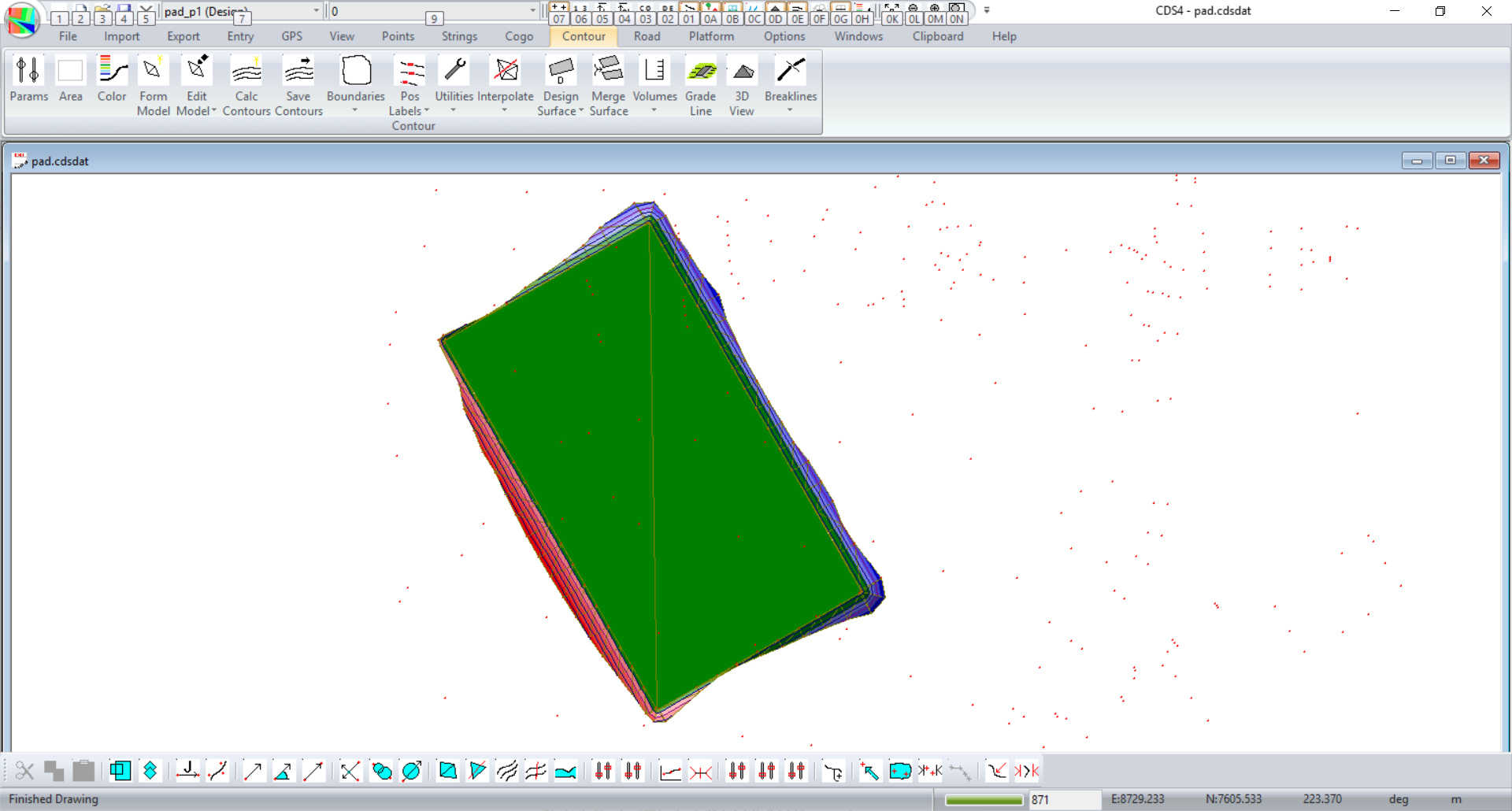
Once you are happy with the design then click on Platform -> Merge. A new triangular surface is created. You should turn off the platform display. Look under the View menu and you can see the "Platforms" icon. If you change to the new surface you can display contours, height displays etc.
If you have multiple platforms then the procedure is the same. You can click within the pad to select or go into the Platform -> Parameters and change to the appropriate pad. Make sure you give them unique names so everyone knows which platform you are referring to.
So we have a natural surface and the appropriate design surface for the pad. We can do a formal volume between 3 surfaces. We can export the job to Ezigrade if you want to grade the pad with Trimble, Topcon, Agguide etc. Or export as an XML for many civil grading solutions. You can even stake out the design for a more manual solution.
|