| < Previous page | Next page > |
|
The Introduction Continues
The purpose of this example is to continue your introduction to the use of the various facilities in , and here in the guise of designing a mock subdivision you will learn how to
Start CDS from the desktop.
In this example, you will learn how to start a Job from scratch, rather than work on an existing job as you did in the first example.
Creating a New Job
Pull down the File menu, and select New.
You wish to start new Job with an ID of "IN2", and you should store it in the folder “Foresoft\cds3\Tutor, so make sure the folder is set to that location and type in a Filename of "in2" to replace the ‘*.data’ which appears.
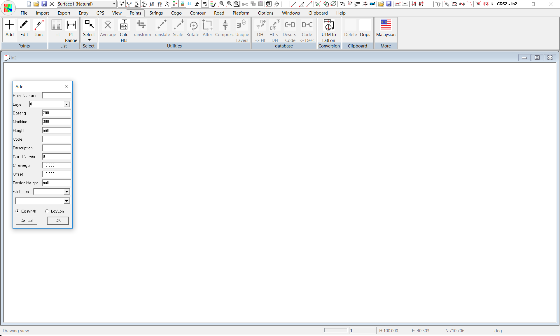
Adding Points
If you pull down the Points Menu, you will see the option for Add Points, and you should select it.
You will notice that your cursor now becomes a cross rather than the arrow you had previously.
If you watch the Status Bar at the bottom of the screen as you move the cursor around you will see that the coordinates update as the cursor moves around the screen.
We wish to Add in Point 1 with coordinates of East 200 and North 300.
You could, if you wanted, move the cursor carefully until those coordinates were displayed, and then select the point, but it is not very practical to do so. Instead you can simply position the cursor somewhere near where you want the point to be and select a point by pressing the Left mouse button.
A dialogue box will appear as seen below, and you should simply type in values of 200 for East and 300 for North and then Select OK.
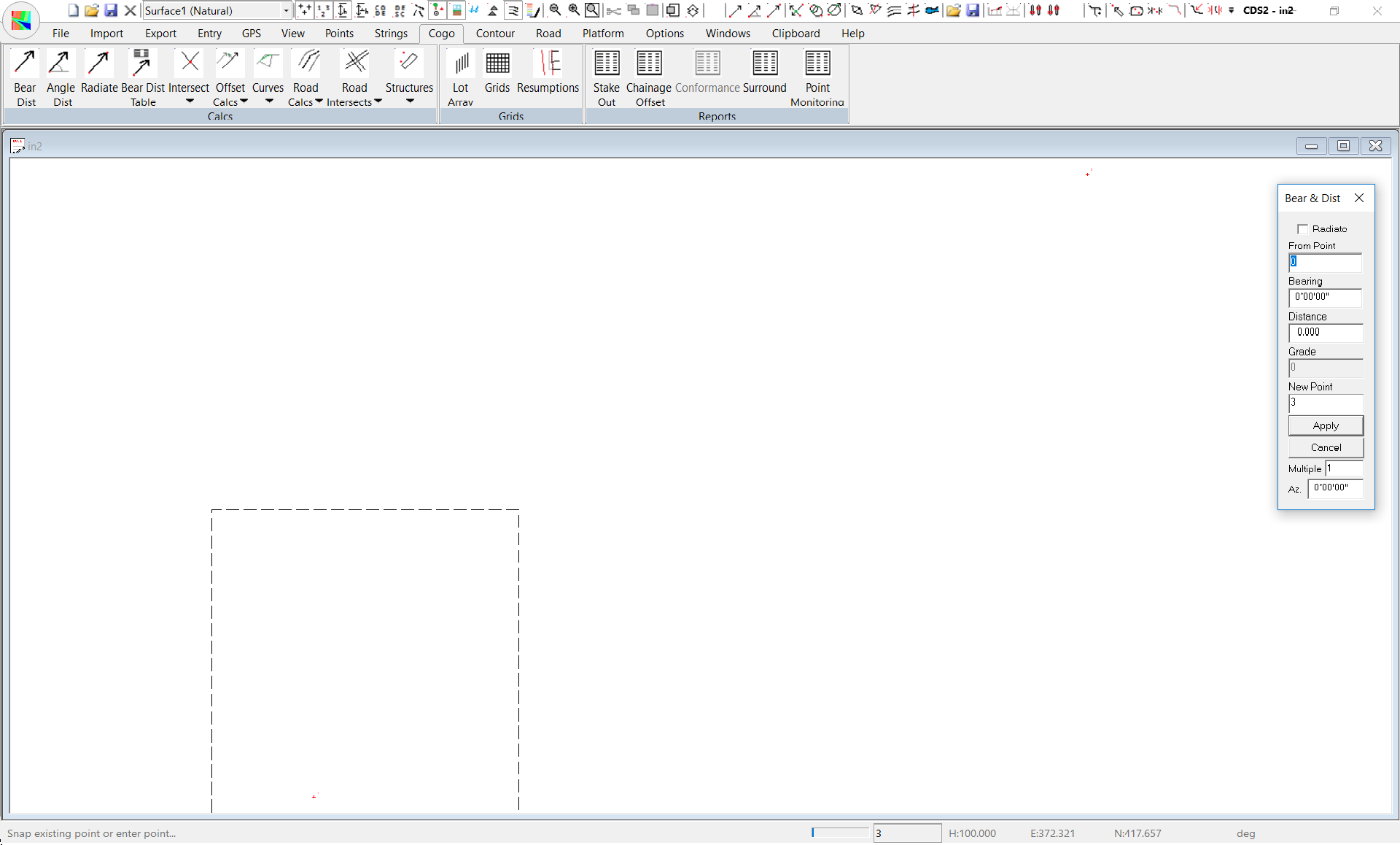
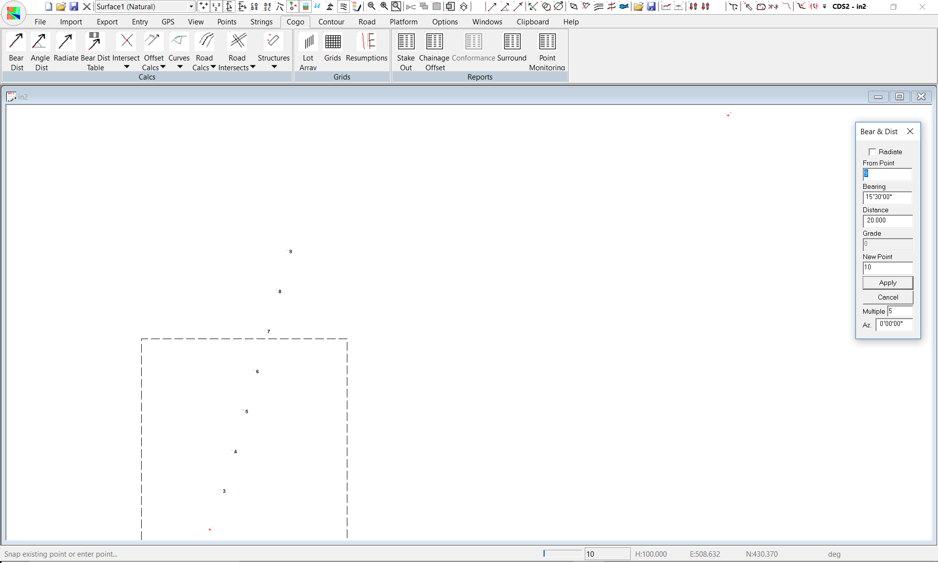
Calculate using Bearing & Distance
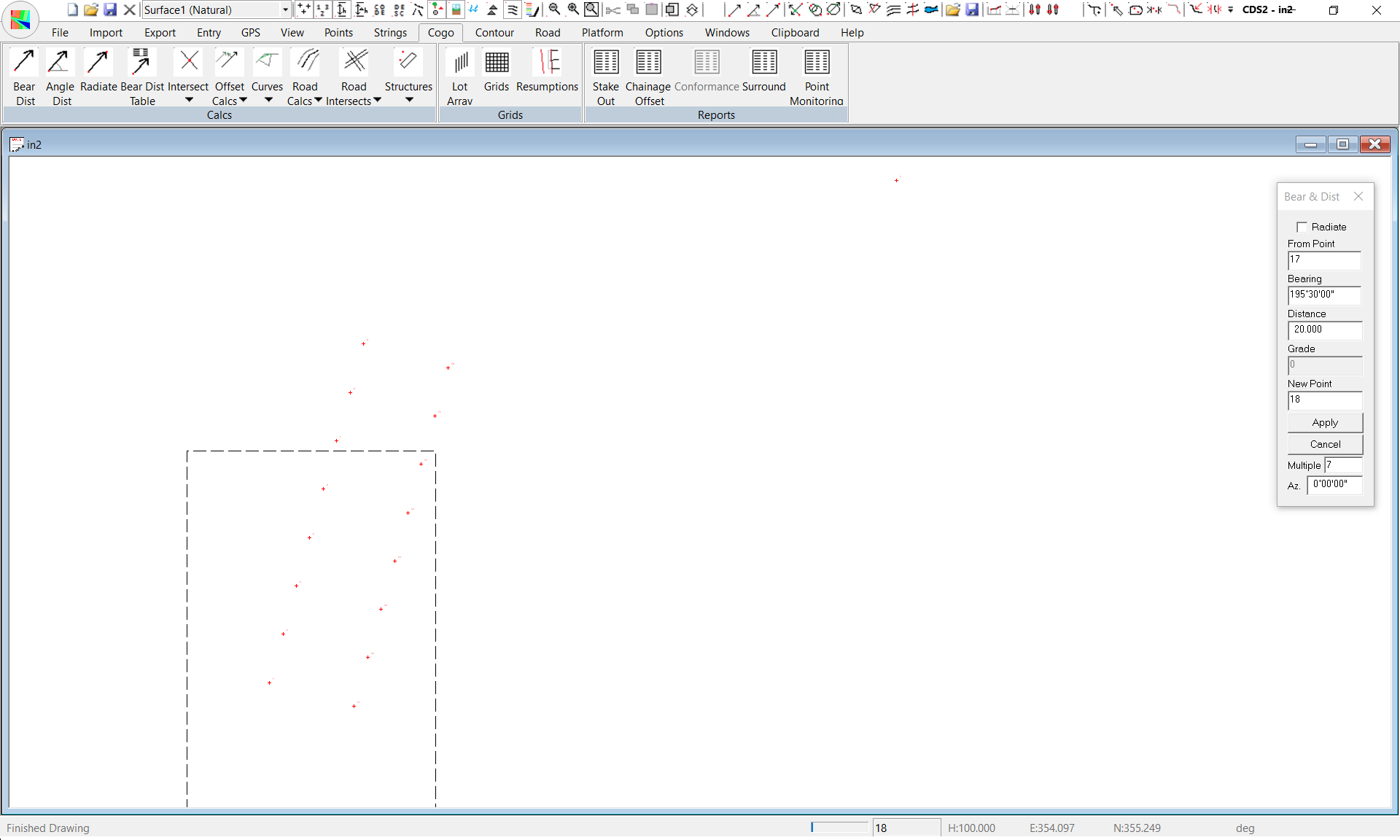
Now pull down the Cogo Menu and select Bearing & Distance.
If you look now at the dialogue box, you will see that the “From Point” has changed to 3 and the new point has changed to 4 which is what we intend.
Both bearing and distance fields have retained the values you used, so if you wish to calculate another point along the same bearing at a distance of 20 metres on from point 3 you need only select the Apply button.In this example, that is exactly what we wish to do, so click on Apply and you will see Point 4 appear on the screen.
This method is fine if you only have one or two ‘frontages’ you wish to calculate, however in this example we need to calculate another 5 points along the line, and there is a more efficient way to achieve this that by clicking apply five times. If you look below the “Apply” button you will see a field titled Multiple.
It is designed to be used where you wish to calculate multiple points along the same bearing, each the same distance apart which is something which surveyors need to do regularly when designing subdivision layouts (and Engineers do when laying out buildings, footings and the like).
Now, we do not want the Multiple calculations to continue at the moment, so set the multiple value back to 1 and then click on the Apply button to position Point 10.
Now close down the Bearing and Distance box, either with the Cancel button, or the X icon.
Now use Zoom (either press Z, or select the magnifying glass icon), and put a window around this batch of points you have just calculated to get a screen similar to that above. Next we need to add in some lines or Strings to show the boundaries of the lots we have just created.
However, the ability to differentiate between points and lines gives you a considerable degree of flexibility in what you have displayed or printed at any time. As an example, consider you were working on a project such as a subdivision that is to be built in stages. It is conceivable that you might wish to place all the Points representing corners of the blocks onto a layer called “Corner” for example.
If all the strings or lines were placed on the one layer called corners, it would be difficult to simply look at the blocks in Stage 3. However, if you use folders named Stage1, Stage2 and Stage3 for storing the relevant strings, it now becomes a simple matter to only display the blocks in Stage 3 by turning that folder ON and all the other folders off. If you wish to place the string in an existing folder you can use the pull down option to see the existing folder names, and select the one that suits your purposes. If you wish to create a new folder, simply type the name of the folder into the space provided.
2. Layers
As well as the folder, the Layer attribute gives you an additional means of grouping strings of the same type together and then easily determining how all members of that class will be displayed/printed.
As an example of some uses of this facility, consider a subdivision that contains lots of different sizes as laid down under zoning guidelines. Say for example you had “normal” size lots, “super” lots and other lots to be used as “parks”. If you assigned the relevant strings around the boundaries of these lots to classes, you could then easily have all “Super” lots filled in and coloured red, all “Normal” lots filled in blue, and the “Park” lots coloured in green. In addition, you might choose to put all the centrelines of the roads within the subdivision into a class called “CL”. You could then decide that all strings in the class CL should be drawn with Chainages plotted along them at the half angle offset to the sting
3. Why have both Folders and Layers?
Simply to give you greater flexibility in how your job is controlled. If we continue the Staged development analogy from the Folders, the Layer is the overriding attribute that determines how all strings in a particular class will be shown. The Folder can then be used to determine which strings belonging to a particular class will be displayed or printed at any given time.
4. The String ID
You need to give each string a name, or a number, or, in Foresight terminology an ID. The string ID can be any combination of the letters A through Z and the numbers 0 through 9, and we strongly recommend that you do not include any characters other than these in string names. It is possible to have more than one string with the same ID in a job; though it is not necessarily recomended.
Back into Action
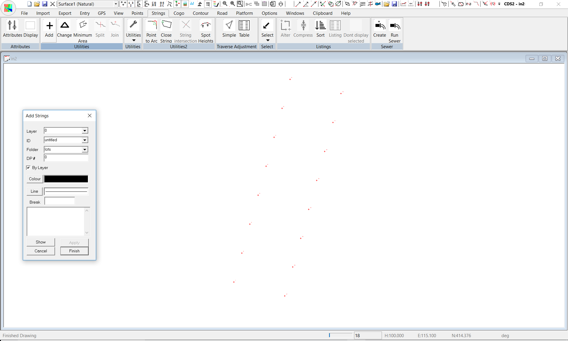
In the Field entitled Folder, you should see the name “lots”. You should be aware that you can store the string definitions in any folder you choose, but the default name of lots will be fine for this example, so ignore the folder field for the moment and concentrate on the String ID field. You MUST give each string you enter an ID which can be either a name, or a number, or a combination of the two. Here we are creating lots, or parcels of land and traditionally these are numbered, so lets start with and ID of Lot 1.
Type “Lot 1” into the field. At this stage, we are not too concerned with Layers, so simply leave the default Layer of 0. Likewise, we do not yet have a Deposited Plan, so leave that number blank. Again, we are not too worried about Pens or Linetypes at this stage, so skip over them and focus on the ‘entry window’. All that is required is that you enter each of the point numbers that make up the string. You may type in the numbers if you wish, and if you choose to do so you should separate each two numbers with a comma.
If the point numbers displayed are too small. Then click on View -> Parameters and change the text size of the point number.
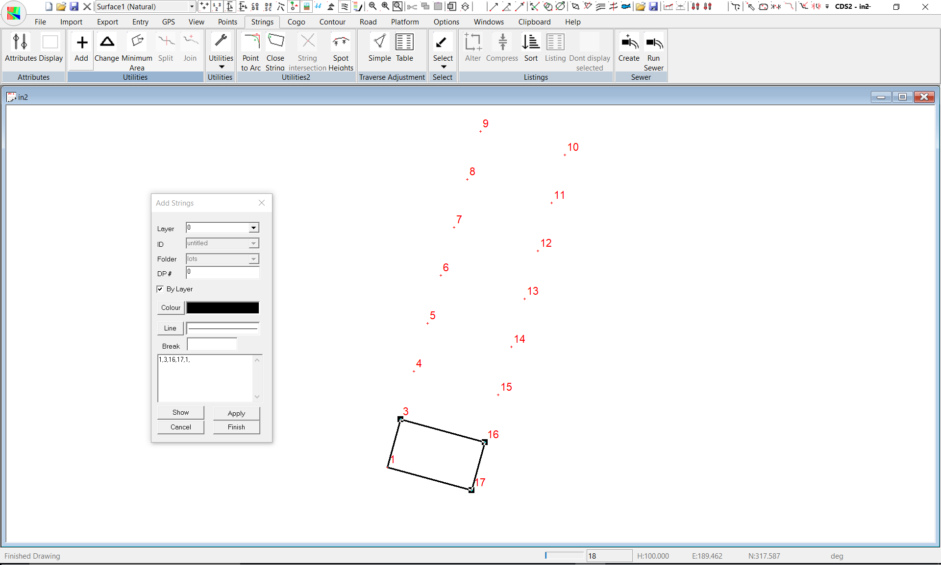
Alternatively, you can point to the points you require with the cursor. In this case, the string with an ID of Lot 1 is made up of numbers 1,3,16,17,1 so you should enter them into the entry window.
You will note that the start point (i.e. 1) has been entered again as the end point in this string and this forms what we term a “closed string”. If you wish to be able to determine the area enclosed by a string, you must use a ‘closed string’. Once the numbers are entered or picked from the screen, the string will be drawn on the screen for you to see, and as you enter each new number the next segment of the string will be drawn.
Radiate
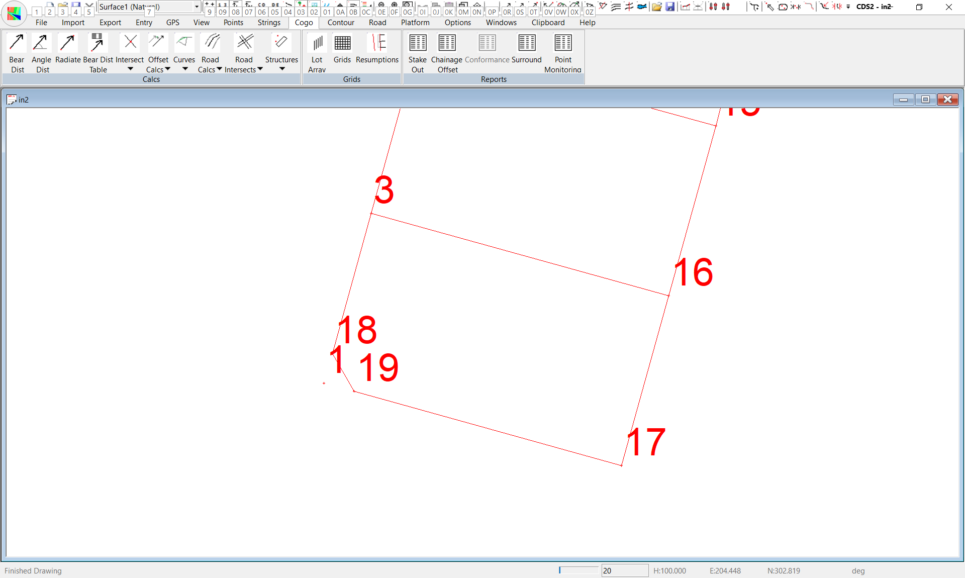
To calculate the splay points you should use the Radiate option from the Cogo menu, so pull down Cogo, and select Radiate. The From Point should be 1 which you can either point to with the cursor, or type in from the keyboard. The first bearing is 15°30’ for a distance of 3.5 metres to calculate Point 18. Now you will notice with radiate that the “From Point” will remain at Point 1 rather than leaping to the last point calculated as in the Bearing & Distance routine we used earlier. Position the cursor in the Bearing field, and press the “R” key to swing the existing bearing 90° to the right. Now select Apply and you will see Point 19 calculated. Now close Radiate.
Change a String.
Next you need to change the existing definition of the string with the ID of Lot 1. Pull down the Strings Menu and select Change. The dialogue box will appear waiting for you to identify the string you wish to change. You may pull down the list of String ID’s if you wish, and select Lot 1 from there. Alternatively you may select it by Pointing with your cursor to the string you want. If you do wish to point, it is important that you point to a unique part of the string. For instance, here if you wish to point to one of the side boundaries, you would point to the line between points 1 and 17 rather than the line between point 3 and 16 because this line 3-16 is also part of Lot 2, and so by definition is not unique to Lot 1. Once you have identified the string, the numbers 1,3,16,17,1 will appear and you should position your cursor in this field and alter the numbers to read 19,18,3,16,17,19. Then press the Show button to ensure you have specified it correctly, followed by Apply to save the new definition of Lot 1.
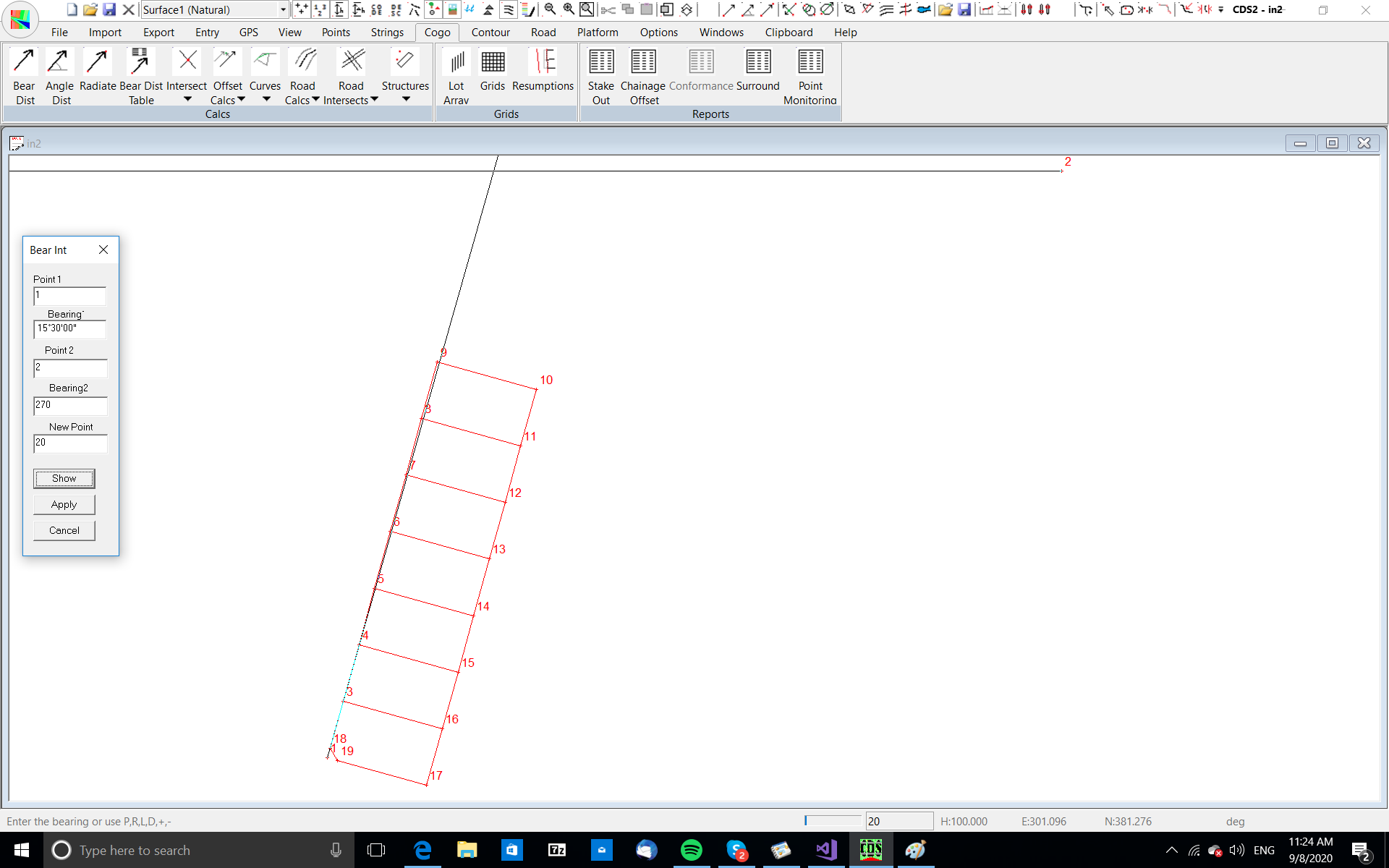
Intersect Two Bearings.
Pull Down the Cogo Menu and select the option titled Intersect Bearing & Distance, and then select the item titled 2 Bearing Intersection.
Join
Press the ‘J’ key to instigate a Join. Enter the points 9 and 20 respectively and calculate as seen in the screen at right. As well as noting the distance, it is very important that you get in the habit of checking that the bearing is also correct, and here it should be at 15°30’. Keep in mind as you are calculating that it is relatively easy to hit a wrong key, and for example if you had inadvertently keyed 15.50 for the bearing when you created point 20, you wouldn’t see the difference visually.
If you develop the habit of checking often, you won’t find yourself in a mess later on trying to unravel where you actually made the error. While in this mode it would be worthwhile to check the join between 20 and 2 which should give a bearing of 90 and a distance of 194.535. Enough of the checking and back on with the calculations.
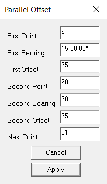
Now with a distance of 67.5 metres left to the corner, it should be reasonably clear that you can either get 3 full blocks and a ‘funny little bit’, or two blocks with the possibility of something decent left on the corner. Before we go much further, we need to see where we can get a full depth block off both the street running North-South and the street running East West, and we can determine this by using an offset of 35 parallel to both streets.
Parallel Offset Calculation
Pull down the Cogo menu, select the item entitled Offset Calcs, and then select the Parallel Offset option.
A dialogue box will appear as seen in the screen below right, and the values are as follows.
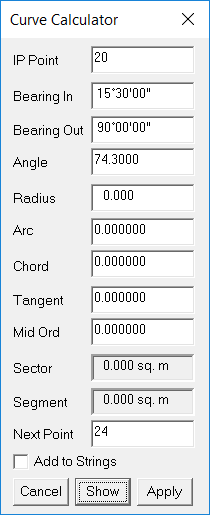
Calculating a Curve
Pull Down the Cogo Menu and select Curves followed by IP & Radius. Note that if it overlaps your points you can Drag the Dialog box over to the right hand side of the screen so it is out of the way.
Your IP Point is 20.
The incoming Bearing is 15°30 and the Outgoing Bearing is 90°
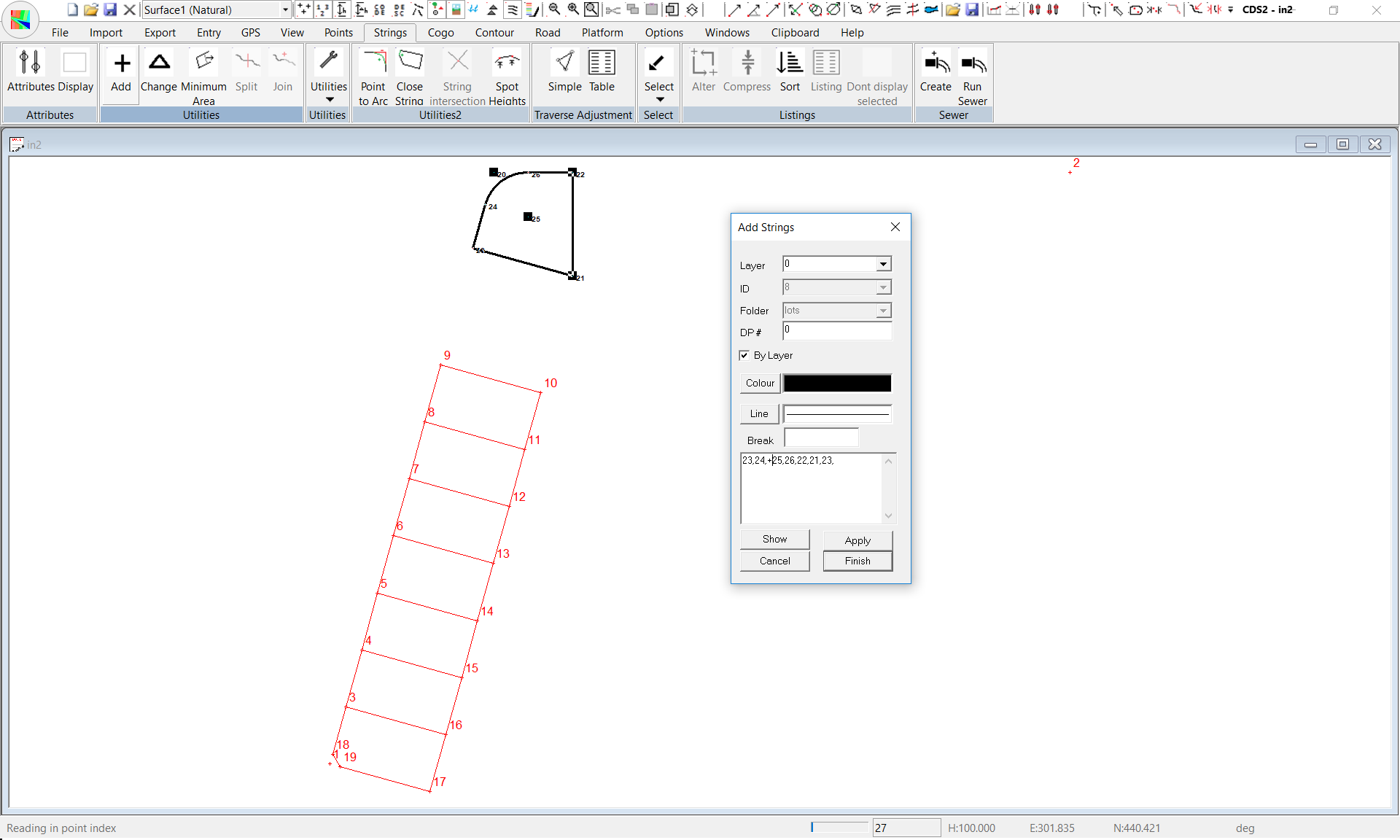
Adding a Curved String
Now that we have calculated all the points for the park, it is time to define its boundary as a string. Pull down the Strings Menu and Select Add. (If necessary, you can drag the dialog box to the right to clear the area you are interested in. Use the Folder “Lots” and use an ID of ‘Park’. Enter a Layer of Park.
You have learnt earlier in this exercise how to define Strings, so the only difference here is that the string has a curve in it. To define a curve, you enter a tangent point, the centre point preceded by a + or a - sign depending on whether the curve is;
Right handed or clockwise about the centre ( + ), or,
left handed or anti-clockwise about the centre ( - ).
It is also recommended that you do not start defining a string on a curve tangent point.
So here the points you need are 23, 24,+25, 26, 22,21,23.
Listing Strings and Areas.
It is often necessary to have a list of the various strings you have defined, and since the strings here define boundaries of parcels of land, it is also useful to have a record of the areas of each of the parcels.
To do this we first need to select the strings we are interested in, and then list them, so pull down the Strings Menu and highlight the Select Option. You will see that there are a number of methods of selecting the strings you require, and for this exercise we will show you how to use the Range facility to select. If you pick Select a Range, you will see that each of the folders in the job is listed. If you wish to simply select all of the strings in a particular folder you can ‘tick’ the box adjacent to the name of the folder. If you wish to see what strings are in a particular folder, you can select the “plus” box to the left of the folder name, and this will expand the display to show a view of all the strings in that folder. Once you have selected the strings you require, pick OK.
Next pull down the Strings menu again, and now pick Listings. You will then be asked which type of listing you require, and a Full Listing is normal for presentation, so check that button.
Next you will see the Wordpad program open a window, and the listing will be presented. You can use the Wordpad facilities to change fonts etc if you wish, and once you are happy with the format you should Save the document.
The format of the listing can be seen from the sample below.
JOB NAME: C:\CDS\in2Date: 12/06/1997
POINT BEARING DISTANCE EASTING NORTHING
_________________________________________________________________________
Folder: lots String ID: Lot 2
3 15~29'59" 20.000 205.345 319.273
4 105~29'59" 35.000 210.690 338.545
15 195~29'59" 20.000 244.417 329.192
16 285~29'59" 35.000 239.072 309.919
3 205.345 319.273
PERIMETER 110.001 m.
AREA is 700.000 m. sq
Folder: lots String ID: Lot 3
4 15~29'59" 20.000 210.690 338.545
5 105~29'59" 35.000 216.034 357.818
14 195~29'59" 20.000 249.762 348.464
15 285~29'59" 35.000 244.417 329.192
4 210.690 338.545
PERIMETER 110.000 m.
AREA is 700.000 m. sq
Folder: lots String ID: Lot 1
18 15~29'59" 16.500 200.935 303.373
3 105~29'59" 35.000 205.345 319.273
16 195~29'59" 20.000 239.072 309.919
17 285~29'59" 31.500 233.727 290.647
19 330~29'59" 4.950 203.373 299.065
18 200.935 303.373
PERIMETER 107.950 m.
AREA is 693.882 m. sq
Folder: lots String ID: Park
23 15~30'00" 15.209 248.352 474.353
24 105~30'04" 15.000 252.417 489.009
+ 25 0~00'00" 15.000 266.871 485.000
26 89~59'59" 15.209 266.871 500.000
22 180~00'00" 35.000 282.080 500.000
21 285~29'59" 35.000 282.080 465.000
23 248.352 474.353
PERIMETER 119.921 m.
AREA is 906.699 m. sq
|