|
Strings
In this tutorial you will learn how to
-
assign strings to 'layers'
-
use 'layers' to plot solid colors in closed strings
-
use layers to specify which attributes are plotted on strings
-
use layers to 'hatch' closed strings.
|
|
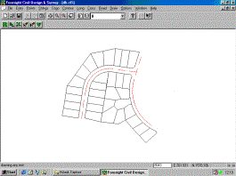
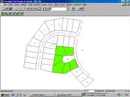
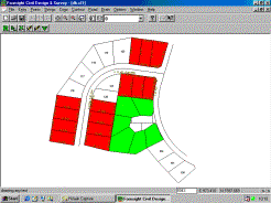
Open Job “cl1” in your Tutor directory and maximise the screen.
The screen should appear as shown. If it does not, try Zoom Extents to get the view you need.
To show you the first glimpse of what you can achieve, we have already allocated some of the parcels into particular classes of strings.
|
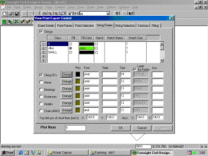
Pull down the Strings menu and select String Attributes.
|
|
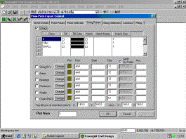
The screen should appear as seen at left.
You will see here that we have three classes named 0, villas and small respectively.
Don’t be too concerned about where the names came from, as the names themselves are random and of little importance.
|
Applying Solid Fills
As a first example of what you can do, select the “Fill Button” on the line which deals with the “villas’ class, and you will see the box is then crossed to indicate that you want these strings to be filled in with a solid colour . You can also hatch, but that will be covered later.
|
|
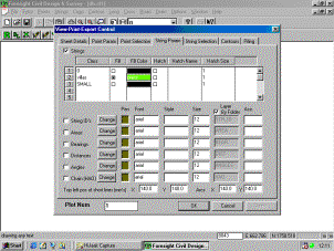
At this stage we will settle for a colour, so click on the solid black bar to bring up the palette of available colours.
Pick one of the green colours which takes your fancy and then click OK.
The screen will return and you will see the Fill Colour of your choice is now shown, and the screen will appear as seen at right.
|
|
|
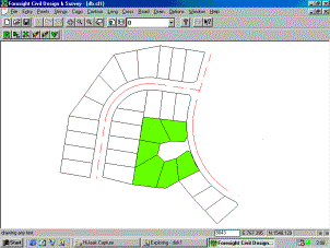
If you now select OK, you will return to the screen that should now appear similar to that at right.
Obviously you could do the same thing to apply different colours to the other classes, but we have other things in store.
|
Specifying String Attributes to be Displayed
As well as allowing you to control what colour your parcels are filled with, the class table also allows you to set the String parameters for each class.
Select the Strings menu and again select String Attributes.
This time with Class Name 0 highlighted, move your cursor down and turn ON String ID’s by clicking in the box.
You can also set the colour of the pen and the size and font that the ID’s will be drawn in by selecting the “Change button”
The Size of the font is particularly important if you wish to be able to see things on the screen, and you need to realise that these attributes will be displayed on the screen at the same relative size that they will be plotted at.
|
|
While we don’t actually scale the screen to the particular plot scale, the String ID’s, bearings, distances and the like are all drawn at a size which shows you how they will appear relative to the plot at the scale selected on the Plot Parameters Screen. Perhaps it might be clearer if I demonstrate rather than describe.
|
Select the Change button, and set Arial font in Black at a size of 18 Points.
The screen should appear as seen at right.
Now press OK to return to the job which should appear as seen on top of the next page.
|
|
If you look closely, you will see some indication of figures in the middle of some of the parcels where you would expect to see a Lot Number (or indeed a String ID as we call them).
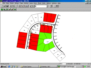
Now pull down the File menu, select Plot parameters, and set the scale to be 1:1000. Then press OK.
|
The screen will now appear as below, and you should be able to make out some Lot numbers and some other String ID’s. (at least on the screen, if not on the screen dump)
|
|
Obviously since we have doubled the scale of the drawing, we have effectively halved the size of each parcel.
But the font size has remained constant so it will appear to be twice the size it was previously
Clear isn’t it.?? Don’t worry if it doesn’t lock in immediately, just give it time and think it through and the light will come on.
|
And it is important that the light is on, because this relativity will apply to all the attributes of either points or strings which you choose to plot onto your plans.
You can also play with turning on various combinations of the other available attributes needed to produce the various plan types you encounter.
A Note about Font Sizes.
Traditionally surveyors and engineers have specified text heights in millimetres, but with Windows you need to specify in Point sizes.
In order to be able to convert, I should tell you that 72 points is equal to one inch, or 25.4 millimetres.
So, by a process of simple arithmetic we find that 10 points is near enough to 3.5 millimetres.
Or to put it another way, if you multiply the Point size by 0.35 you will arrive at the size of the text in millimetres.
Different Classes with Different Attributes
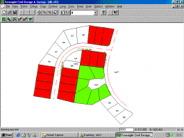
Return to the String Attributes table and this time highlight the Class Name “SMALL”.
|
|
Select the Fill box, and pull down and choose a Red colour.
Then move down and Select the Distances box, and use Change to set a Size of 14 (which should be about 4.9 millimetres).
When you select OK and return to the screen it should appear as shown.
|
Here you will have the following Classes and attributes
Layer 0 – not filled and display String ID’s
Layer ‘villas’ – filled in green with no attribute displayed
Layer “SMALL” – filled in red with distances displayed.
Using Layer to Show Road Centreline
If you look now at the two Road Centrelines in the job, you will see that they still belong to Layer 0, which is the default layer all strings have, unless you specify otherwise.
It is common on engineering plans to show these centrelines with the chainages of the points displayed at the half-angle, and you can achieve this as follows.
First you need to put the strings into a class of their own.
Pull down the Strings menu, highlight Select, and then choose Single String Selection.
You will see your cursor now changes to the string selection crosshair.
Select each of the centrelines shown by ‘clicking on’ part of the line.
NB. for the moment please make sure you only try and select on a straight part of the line – pointing to the arc is not as reliable.
Once the strings have been selected, pull down the Strings menu again, and pick Alter.
A small window will pop up to allow you to alter the Pen, Linetype and Class of all the Selected Strings.
In this case you are only interested in changing the Class, so position your cursor in the Class field and type in Road and then choose OK.
Now go back to your String Attributes, and this time you will see a ‘Road’ Class is now in the table.
Highlight the name Road with your cursor.
Now move down and select the box titled ‘Chain (HAO)’. (The HAO is shorthand for half angle offset).
Change your Font to be black with a font size of 14.
|
|
Select OK, to see the screen at left.
You will see that the chainages will most likely overwrite the details on the front boundaries of the lots, but at this stage we are only interested in showing you how to use the different features.
We make no attempt whatsoever to suggest what combinations of these features you might wish to use at any point in time.
|
Past experience has however shown that you would normally not try to draw an engineering plan with centreline chainages at the same time as you had distances on the boundaries, but we have given up trying to predict what people will and will not do in drawing plans.
Using Hatching.
As well as filling in closed strings with a solid colour, you can also apply a hatching pattern.
If you look at your job you will see a court bowl which has a line across its entrance to close it off.
Select this string by clicking on the line across the neck of the bowl, and then Alter its class to be ‘Bowl’
Next go back to String Attributes and highlight class name Bowl.
Click in the hatch box, and type in a hatch name of “brick” and press enter.
Now press OK and you will see the screen as below.
|
|
Note that at this stage you must type in the name of the hatching pattern that you require.
As the program develops, a pull down list of hatch patterns will be implemented, but as always we prefer to get it working then get it pretty rather than the other way around.
The names of the standard patterns supplied with CDS can be found in your OnLine manual, but you can use any hatch pattern which you find which is compatible with the Autocad standard method of hatching.
|
|
|
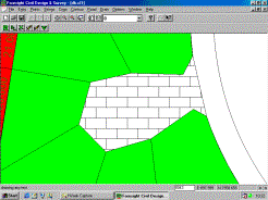
Before you complain that the hatching is not particularly dense, Zoom a window around the area of the court and you should see something like below.
Again, in this exercise I am more interested in identifying the features and showing how to get to them rather than trying to produce a perfect result.
|
I leave it to you to experiment with other hatch patterns and different scaling to see what you can achieve. However, before you start to complain that the hatching facility doesn’t do what Autocad does, let me tell you that I already know, and it was never designed to compete with a full featured CAD package. If you need or want more than is available, export a DWG and use a full CAD package to finish the drawing while we concentrate on the calculation routines that CAD packages don’t have.
|