| < Previous page | Next page > |
|
Symbols
In this Tutorial you will learn
What Are Symbols?
Symbols are standard “drawings’ which can be inserted into any CDS job. Any drawing that is stored in an Acad dwg file can be used as a symbol within CDS. Symbols can be created within CDS. Please see the tutorial appendix that gives an example. Also most Windows based CAD packages (e.g. Autocad, AutocadLT or free NanoCad) can store or export drawings to a dwg file.
How do you Create a Symbol?
Please view the tutorial appendix on Symbol Creation.
Some Basic Concepts
Before you go any further, it is important that you comprehend a couple of simple facts about these symbols you are going to use.
The Size of a Symbol.
The symbol size is defined by how big the symbol is drawn in the dwg. For example if you have drawn a circle with a radius of 1 unit then it will be displayed at a size of meter if in metric mode. If you are displaying an Imperial job then the radius will be 1 foot.
Sizing Symbols
When inserting a symbol you have the option of applying a scaling factor. Inserting at a scale of 2.0 leads to a symbol twice the size.
Scaling Symbols
As well as determining the size of the symbol in real world dimensions, you also need to determine if a particular symbol will be scaled to match the drawing scale when the job is plotted out. Symbols can either be considered as representative or pictorial. For example, a drainage pit, would normally be representative i.e you would like them to be drawn at the correct scale on the plan to represent their true relative size on the ground. Alternatively, there are things such as light poles, or traffic lights or survey permanent marks which you may wish to represent with a symbol which is purely pictorial i.e. it represents the location and identity of the feature, but does not necessarily represent its true size in relation to other features on the plan. For example, the survey mark that we mentioned might be a nail in a kerb. If this nail was 10millimetres across the top, and you tried to represent it at the correct size on a 1:1000 drawing you would not see it, so it would be far more sensible to make its symbol non-scaleable so that it holds the same size regardless of the scale of the drawing. So, armed with these basic concepts it is time for you to try and apply them in a vaguely real situation, and to show you the procedure we will use some of the sample symbols supplied with CDS.
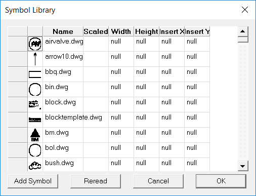
Using the Symbols Supplied.
Inserting a Symbol Manually
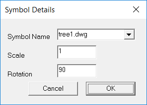
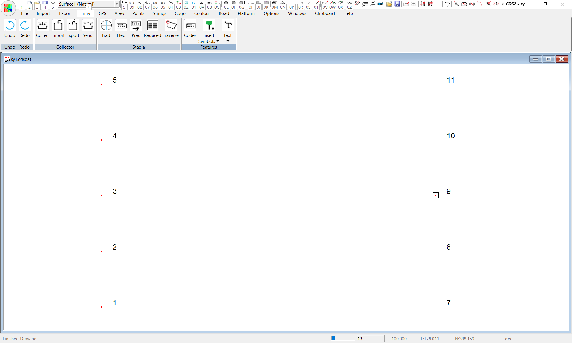
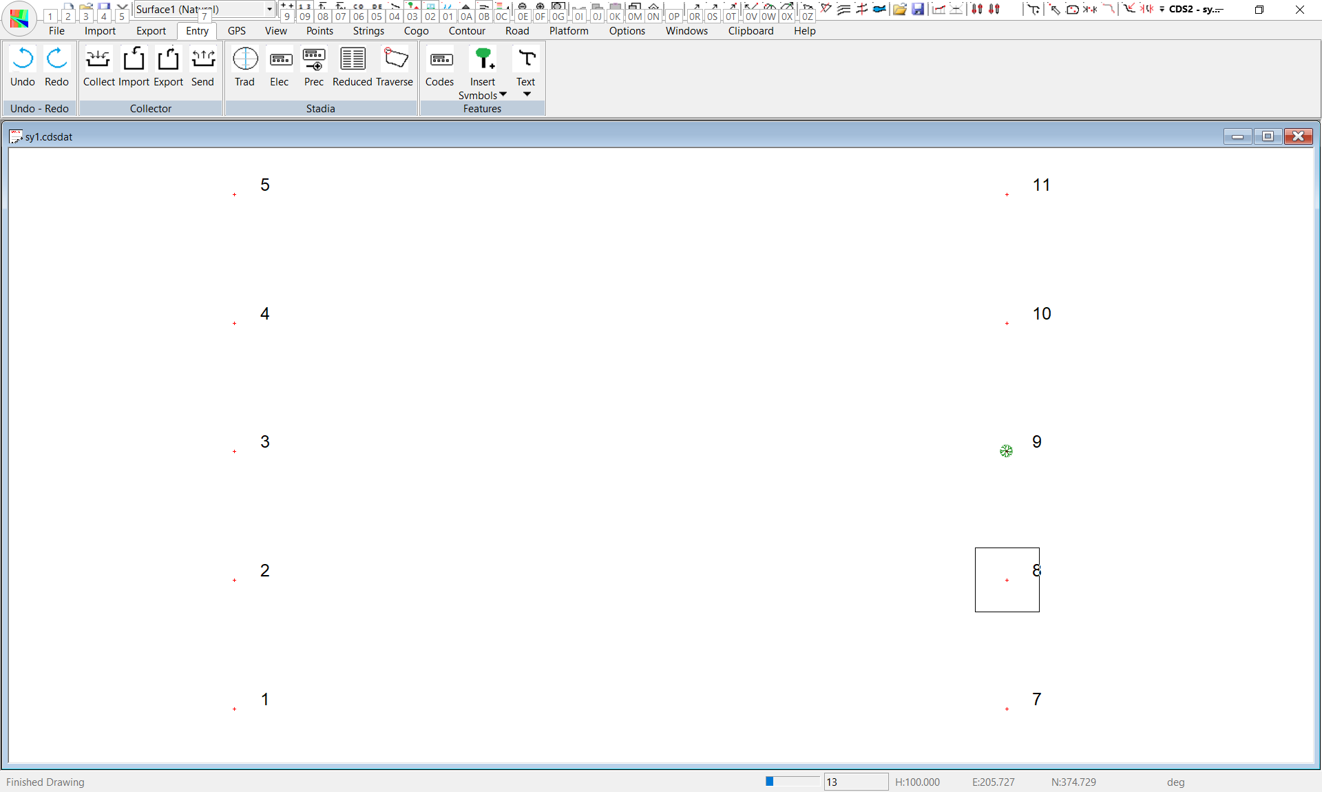
First off we wish to insert a symbol called TREE1.
Don’t be concerned. For reasons of speed, only the surrounding rectangle is shown when you are placing the symbol. If you redraw the screen by pressing the “D’” key, the symbol should appear. If it does not, you need to make sure symbols are turned. Click on View menu and make sure Symbols is highlighted.
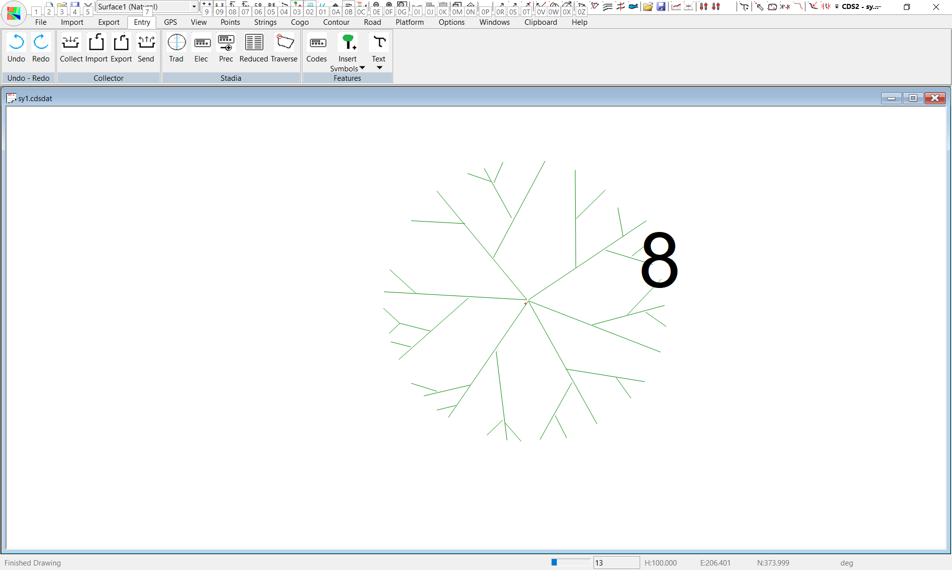
When the screen reappears, you will see the rough outline of a tree appears in place of the square, and you may zoom in to get a closer look if you wish.
Locking the symbol over a point
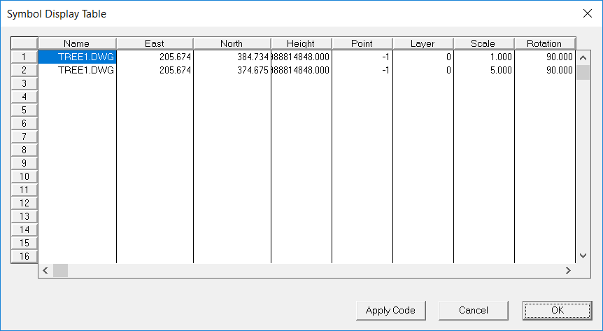
Pull down the Entry Menu, select Symbols and then select Symbol. Display to see a screen like that below.
(You will see later in this Tutorial that you can also use Feature Codes to position symbols over points) NOTE: you may, if you wish, come directly to this table and simply type in the name of the symbol, the size and the point to locate it over if you wish to manually position symbols over existing database points. You can also use this table to alter the sizing of a symbol you have already placed.
Delete a Symbol
In the event that you wish to delete a symbol that you have placed, you also come directly to this option. Use your cursor to select the Line Number of the symbol you wish to delete. I.e. click on the line number on the left-hand side. You will see the entire line is highlighted or selected, and you can then simply press the Delete key to remove the particular symbol. Be careful, since there is no undo facility available. Next it is time to learn how to use feature codes to insert symbols automatically.
Insert a Symbol using the Code Library.
As well as inserting individual symbols as we have already done, you can ‘automate’ the process by using codes and the code library if you wish. To do this, it is necessary for the points to be coded with ‘feature codes’ and for you to set up a code library defining what you wish to do with those codes.
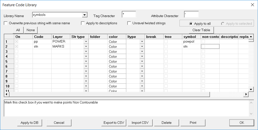
In Job SY1, we have already supplied codes for points 3 and 5, and you can check on these codes by either using Modes - Display to turn them on, or by using the “?” key to query the points. (You should find that Point 3 has a code of PP to indicate a power pole, and Point 5 has a code of STN to indicate a Station.) So, we have complied with the first of the requirements in that we have some points with codes. Now we need to set up a code library. Pull down the Entry Menu, and select Feature Codes. The screen should appear as below.
Type in ‘POWPOL’ to indicate that wherever the program finds a point with a code of PP it is to insert the symbol ‘powpol’. Then press enter or Tab to move the cursor into the layer column.
Type in ‘Power’ to indicate that all points with this particular code are to be assigned to a layer called power. The cursor will move to the Folder column, but since we are not interested in strings in this example we have no need for a string folder, so simply press Tab to move past it and leave it blank. The cursor should now be in the Code column again, so type in “STN”, set it as a Point code, define the action of ‘S=STN’ and assign a layer of ‘MARKS’. Again Tab past the Folder column to finish off the line.
At this point you are ready to now apply the codes to the points in the database, so select the ‘Apply to DB’ button. A prompt will appear to inform you that the library has been applied, so click on OK to confirm the message and proceed.
Then select the OK option to save the code library details and close down the window.
Sizing Symbols with the Code Library
You already know from your tree exploits that you can change the size of a symbol within the symbol library itself, and now you will see another method for achieving the same result. In this instance, power poles can be of differing sizes, so we don’t wish to use the symbol library to reduce our symbol to a uniform size. Instead, you need to size the symbols as they are inserted and you can achieve this as follows. Pull down the Entry menu and Select Feature Codes. Use the pull down arrow and select a Library name of SYMBOLS, and you should see your code library again.
Move the cursor into the Action column on the first line, and position the cursor at the end of the entry. What you wish to achieve here is to have a power pole drawn with a diameter of 300 mm.
To achieve this, you need to Magnify or Multiply the base scale of 1 metre by a factor of 0.3. So, after the word ‘powpol’ you place the ‘-‘ sign to indicate to the program that attributes are following. The attribute in thus case is ‘M0.3’. Your symbol name entry should now read 'POWPOL-M0.3’ Next select the “Apply to DB” option.
When you redraw your screen with any of the zoom or pan functions, you will see that the symbol representing the power Pole has now been reduced in size so that it appears correct in relationship to the tree over Point 9 that you compared it to before.
Representing Pictorial Symbols
If you recall the basic concepts at the start of this tutorial, you will remember that we said that a pictorial symbol is one which is inserted at a particular size which is generally not representative of its size on the ground, and that it is generally not scaled up and down with the scale of the final plot. The symbol signifying the Station which is inserted over Point 5 is a case in point. Here the Station is in fact a Peg which is 50 millimetres square, but if we tried to draw the symbol to that particular size we would have difficulty finding it. The size you choose will depend largely on the scale of the drawings you are going to produce, and to your particular aesthetic values, so please treat the number used below as a guide only, and use your own values as you see fit.
For example, if you normally produced drawings at a scales of 1:500 and 1:1000, you would probably need to have your station symbol plotted at about 4 millimetres on the plan, (rather than the 0.5 millimetres at 1:1000 if you left it as representative.)
You also wish to indicate that this symbol is NOT to be scaled with the plan scale, but will be drawn at 4 millimetres regardless of the scale of the plan. To achieve this, pull down the Entry Menu, select the Symbols option and then select the Symbol Library option. Scroll down until you find the “STN” symbol. First, ‘uncheck’ the scale box to indicate that it is to stay the same size regardless.
Then enter a “Size” of 4. Why 4 I hear you ask? Because, you set the symbol up as if it were going to be plotted on a 1:1000 plan. If that were the case, and you left it at 1, the square with 1 metre sides holding your symbol would be plotted on the paper with sides of 1 millimetre, whereas you want them to be 4 millimetres.
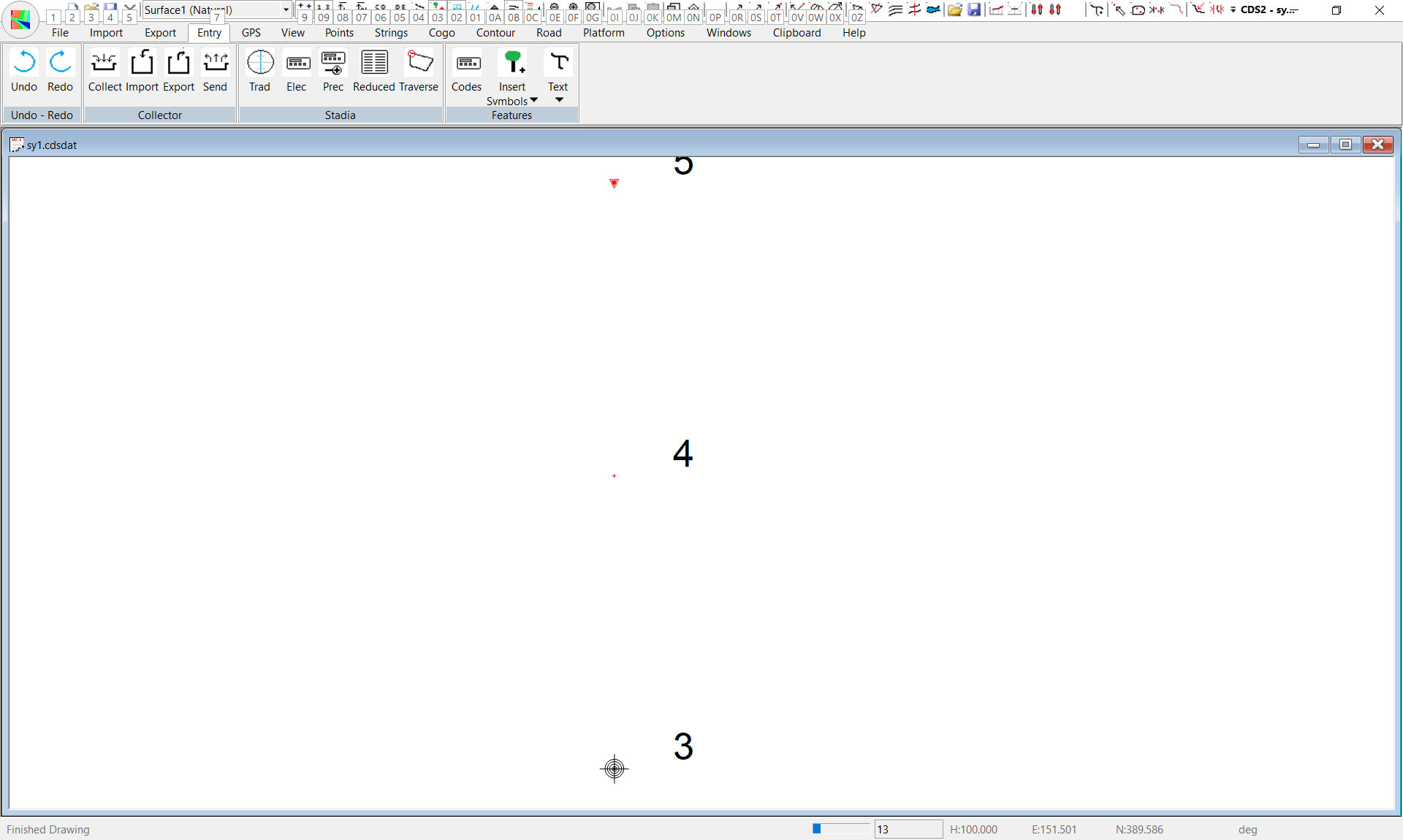
Inserting Text.
If you need to insert Descriptive text into the job for things such as Road Names or construction notes or Tree descriptions, you can do so in the following manner.
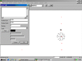
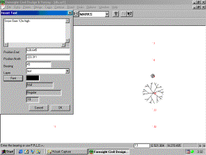
Pull down the Entry menu, select Text, and then select Insert Text.
Here we wish to type in a description of “Snow Gum 12 m high” to the right of the tree over point 10. So first type the string of text into the text window. You need to enter in the bearing for the text. You may either type in a bearing in the usual format, or you can use the “P” option to get the bearing between two points, or you can use the ‘D’ option to draw the bearing you require on the screen In this case, we will use a bearing of 45, so type that in. You now can enter in the layer name to store the text on, and in this case ‘text’ will be adequate
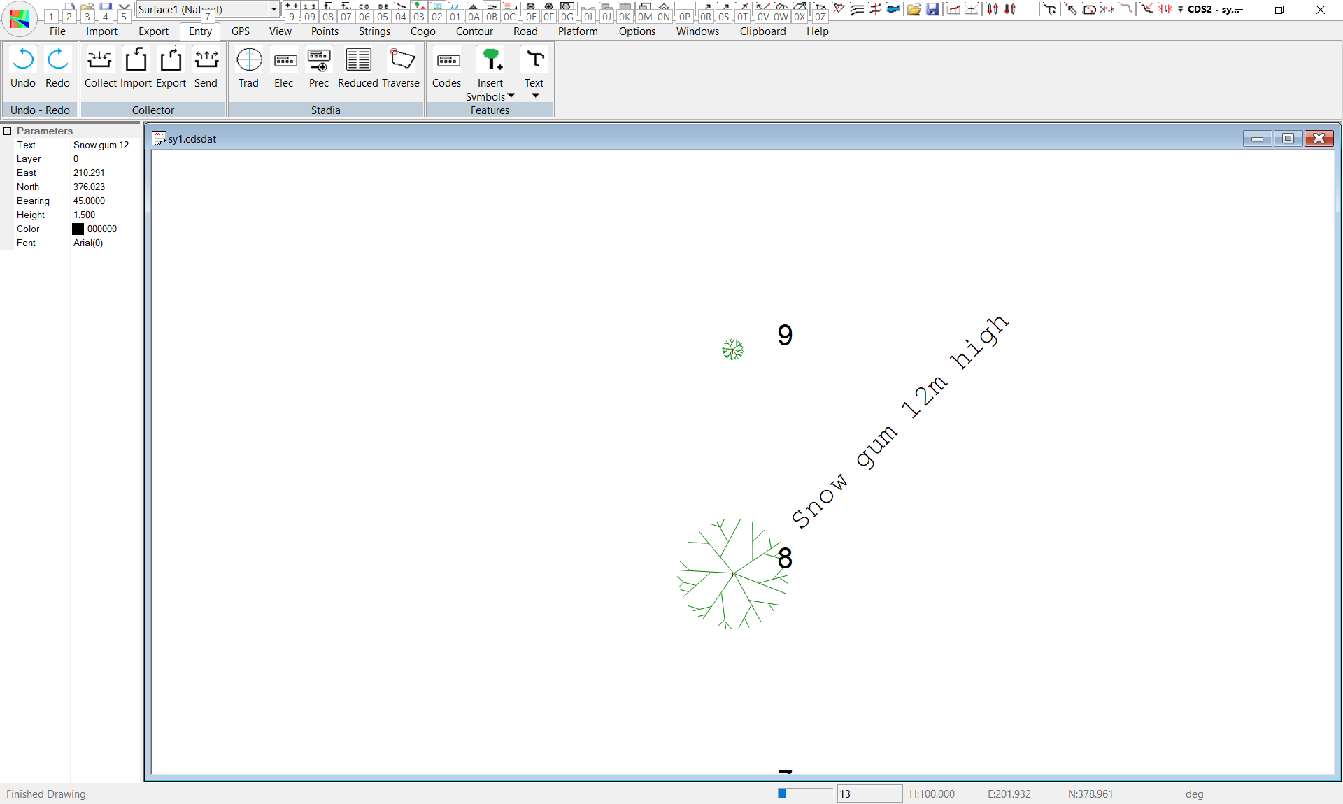
Armed with this knowledge, you can now insert all manner of text onto your drawings, but I do advise that if you wish to get into serious schedules, and tables of text and the like you are much better advised to do it in your CAD package. You can select this text from the screen and drag it as necessary.
|