| < Previous page | Next page > |
|
Housing Estate Tutorial
This tutorial uses the functions found in the Housing Estate Design section; under the Platforms main heading. They are grouped together under the generic term Estate.
After lengthy consultation with a number of designers to determine current best practice, Estate was designed and implemented in such a way to computerize the best aspects of the time proven manual process.
Estate follows the iterative manual process commonly used by estate designers in which the following major steps were identified.
Estate works in conjunction with CDS-Cogo and CDS-Model to provide a cost-effective tool to solve a time consuming problem.
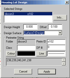
House Lot Design
You select individual lots, or a group of adjoining lots by pointing to them on the screen.
You then enter your required design level and all the points contained in the selected lots are automatically updated.
To overcome the potential problem where adjoining lots are at different levels, CDS-Estate creates an internal perimeter of the chosen group of lots, and offsets it by an amount you specify.
This small offset inside each particular 'design pad' is essential to avoid the 'vertical wall ambiguity' that can cause problems or create errors in all terrain modelling packages.
Road Junction Design
The Road Junction Design provides a tabular entry format to allow you to quickly and easily define the location and required design level of all road junction points.
You simply enter the distance and offset relative to existing block corner points into the table, and all points are calculated and stored in a simple operation.
If you need to alter road widths, it is a simple matter to alter a value in the table and re-apply it to re-position the junction points.
Road Grading Design.
The Road Grading facility also provides you with a tabular format to allow you to easily specify the width and cross grades for roads within the project.
You specify each road by a string of the junction points defined previously.
You enter the relevant cross fall for each road in tabular format that makes it easy to make changes when design criteria alter.
Once the table is completed and applied, the relevant points, with their correct design levels are added to the database to allow the design model to be formed.
A worked Example
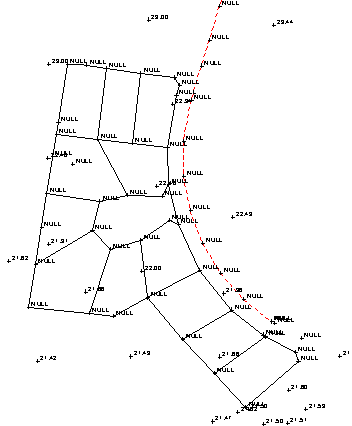
We have been given the following data ( see job "HouseLot" in the tutorial directory) and been asked to design the housing blocks as shown below. The first step is to design the appropriate heights of each individual block. As the land is relatively flat and the blocks relatively small it is best to design each block so that it is flat.
The previous lot string is still high lighted. Hit the escape key to remove it from the selection list. Select the next string of the screen and repeat the process. Do this for every string that is needed to be done.
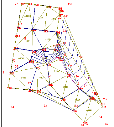
and needs to be investigated. As in all tutorials everything is correct so far. In the job above you will notice that there are some design triangles extending around the edges of the job and also in the bowl area. Select the offending triangles by the select triangles by intersecting line button and highlight them. Hit the delete key and when you are happy reform the triangles. As a final check run your cursor around the job and note that the design heights shown in the bottom right correspond to the actual lot heights as designed.
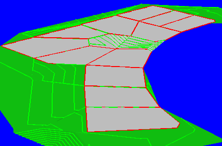
In this case I created a new surface 3 and called it combined. I then merged surface 2 and 3 and viewed this surface 3 in the 3D views window. The following result was obtained. You will notice that no contours cross the lots as expected.
We will also run the volumes between two surfaces here to check the amount of cut and fill that needs to be moved. The result is shown below in italics
Foresight Software Pty Ltd
Calculation of Volumes Between Surfaces
Date: 25/09/2002
Base Job : C:\Program Files\Foresight Software\CDS\TUTOR\db.cl1 Surface: Surface2 (Natural)
Overlay Job: C:\Program Files\Foresight Software\CDS\TUTOR\db.cl1 Surface: Surface5 (Combined)
Fill Surface Area : 11927.363 sq. metres
Fill Area: 11882.669 sq. metres Fill Volume : 1003.978 cubic metres
Cut Surface Area : 9005.500 sq. metres
Cut Area: 8965.006 sq. metres Cut Volume : -1132.602 cubic metres
Matching Surface Area : 2843.928 sq. metres
Matching Area : 2842.974 sq. metres
In this case we are happy with the result. If there is too big a discrepancy it is possible to do the volumes for each lot in turn by specifying a bounding string in the volume between surfaces calculations.
|