| < Previous page | Next page > |
|
This function is presently unsupported.
Road Design through layered material
Please note that this tutorial/white paper refers to the premium version. It is not presently supported for the standard version.
CDS Premium has capabilities for designing roads were it is possible to specify different cut batter grades as the batter passes through the different types of soil or rocks.
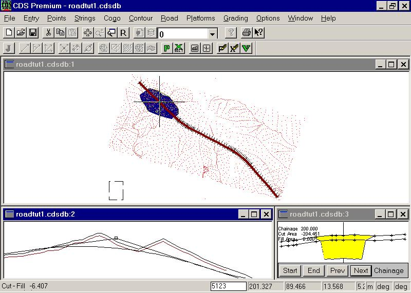
In the following contrived example we follow on from the complete road tutorial example which we have created in an earlier tutorial. In this example we have ascertained that there is a large rocky outcrop that is found about 3 meters under the surface in the area shown. Looking at the screen shot below we can see the triangulated area of the top of the rock.
If you would to download the file for the above job can you please point your web browser to ftp.foresoft.com and download the "multilevel.cab" file. To view the data open up CDS premium and click on the options menu. Select the restore to database and extract the files to your data directory.
In our example we have picked up a series of points numbered from 3000 upwards that correspond to the top of the rock outcrop. We first need to triangulate these data points. From the contour menu select the "Add surface" option and make it a natural surface. We also need to set the point range to be from 3000 upwards. We can now triangulate this new surface. This is surface 4 in our example.
The next step is to calculate some sections through this new surface that correspond to the new top of the rock outcrop. If we use the existing centre line we will lose the information associated with the previous sections and profiles. In CDS Premium the profiles and sections are stored in database tables that are associated with the string. The solution is to create an identical string with a different name. Under the strings menu use the "select" and "single selection". Pick the existing string and press the copy icon. Now press the paste icon. We are prompted for a different folder name. In this example I have changed the folder to lots1.
Under strings now select this string with the select by range option. Attempting to select by pointing on the screen is a bit of a lucky draw as there are two strings in the identical place. We can now run the "Contour"; interpolate profiles and sections. Make sure we use the same chainage intervals so that our sections will correspond for the different surfaces.
We now need to tell the program that we are displaying the two profiles and sections. Select both of the center lines via string select and press the "natural profile definition (Big green P icon) and the section definition (green X). In both of these press the "replace with selected strings" button. We can now view the profiles and sections. Under the windows - tile option tile the screen via "tile by roadworks".
The profile should show the second surface underneath the first. Scrolling through the sections should show up the rocky outcrop in the relevant sections. The next section is to define our new templates. These templates work as follows. In those sections were we have a cut batter that cuts more than 1 section type we need to define a special template. In this case we simply have two cut batters that follow each other. The program knows when it hits the first section. The batter definition stops. If we have another cut batter following the program knows to use this for the next section. This can be repeated for each section that is present. ie 3 soil types then use 3 cut batters one after another. The template we have used is as follows.
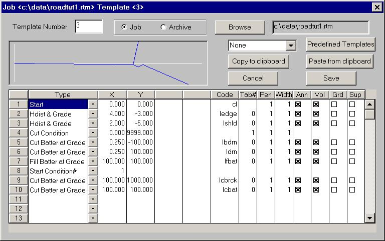
You will notice the line 9 and 10. Line 9 is the cut batter for going through the rock. We have used a batter of 1000% ie nearly vertical. Once we hit the top of the rock we want to batter out at 100%.
From the standard template table it is fairly simple to create this new template. First display a template which is similar to the one you want. Press the "copy to clipboard" button. Change to an empty template by typing in a new number at the top and then press the "copy from clipboard". The template is copied. Left click the mouse on the number 9 to the left of the existing cut batter. Press the insert key and add in a blank line. Fill in the details to make it a cut batter. In our example we have used different left and right batters as we need to code the design points separately from left to right.
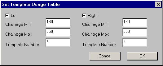
We now need to tell the program which sections we need to use the new templates in. This is best done by inspection. Simply scroll through the sections and note the chainages. In this example we have found that we need to use our new template 3 and 4 from chainage 160 to 350 respectively.
From the section view use the right mouse button and select the "Template Positioning" option. Press the set column button and fill in as below and press the OK key.
For fine tuning you can type directly into the table shown. Scroll through the sections and check that the design is indeed working. You are now in a position to peg out your design in the field.
Approximate Methods
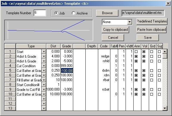
The above discussion assumes that we have the appropriate data that defines the levels of all the different soil seams and rock that we need to design for. In practice we may not have this complete data. We may only know that at chainage 200 for example we know that there is a rock output at a depth of 3 meters. If we are in cut below 3 meters we need to grade up through this material at a different grade to the batter slope. CDS and CDS Premium have a template command that will achieve this. The command is "grade to a cut/fill" and we can specify the grade as well as the depth. In the example above the grade is 1000% while the depth is -3. The template shown below will achieve this result. If the depth changed for different chainages you can also set the tab# (table number) column and fill in a variable template table.
 |