| < Previous page | Next page > |
|
Hatching
The hatching is found in an ascii file called "hatch". It lives in the prolog-v4 directory. You can edit this file directly from the setups menu - "edit view hatch file".
Fill Hatch's
There are two distinct types of hatchings available. The majority of the hatch's can be defined with vectors (ie lines) and there is also a fill option. An example of a fill option entry is
*coal dull, coal example with 10% hatching
fill 10
In this example the hatch name is defined after the '*' and before the ',' Anything after the ',' is a comment and is ignored. The fill pattern consists on a single line - the value is the percentage of the box filled. It is left justified. You can also enter more complicated examples. This example fills in the first 20% the middle 20% and the end 20%. For example:
*coal stony,
fill 20,-20,20,-20,20
Vector Hatch's
All the other hatching patterns used by ProLog are compatible with the hatch pattern originally defined by Autocad. If you have access to any of the patterns which either come with Autocad, or are available in 3rd party hatch libraries you can incorporate those into the file for use with ProLog All hatching for ProLog is defined in a file called “hatch” which is stored in the prolog folder. ( normally "c:\program files\foresoft\prolog-v4") If you wish to alter or add patterns you can do so by using a text editor such as WordPad to edit this file.
Each entry consists of a header line starting with a star or asterisk. Immediately following the star is the name of the hatching style. You may also find a comma followed by an optional description after the comma. If you are creating your own pattern and do not wish to add a description, make sure you do NOT leave a comma after the name.
Following the header line you will see a line, or number of separate lines which define how the program will draw the hatching pattern which must be made up of straight lines only.
Each line description consists of the following structure; angle,x origin,y origin,x distance, ydistance, {dash1,dash2,…} Each line within the definition is a self contained unit which will draw and repeat itself indefinitely
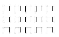
To see how these things go together, we will work with a small example (copied from the Autocad LT manuals) which will draw inverted U’s
The definition is as follows;
*IUS, Inverted U’s
90,0,0,0,1,.5,-.5
0,0,.5,0,1,.5,-.5
270,.5,.5,0,1,.5,-.5
Let’s now look at each of the lines and see what it does.
The angle is specified in degree increments with zero being horizontal to the right, and is measured anti-clockwise, so 90 is vertically up. So, the first thing we see is that the first line is to go vertically up, starting from an origin of 0,0.
The next pair tell us that the next line (of this family) will start at a position 1 unit up in the Y direction. NOTE although described as x-distance and y distance, these values are not absolute X and Y as conventionally known
It is better to say that the Y distance is the distance “in the direction of travel” which the X distance is an offset distance from the direction of travel. The third pair tell us that of this 1 unit which is occupied by the line, half of it (.5) is drawn with the pen down, and the remaining half is drawn with the pen up (-.5) So, this line by itself will result in a dashed line going vertically, consisting of a line for .5 units, a space of .5 units (the pen was up), then another line for .5 units and another gap of .5 units etc.
Let’s now look at the second line in the hatch definition. This is to have an angle of zero so it will go horizontal and form the Top Bar of the inverted U. Its origin is specified as 0,.5 so it will commence drawing .5 units up from the absolute origin. (this is at the top of the line drawn by the first line in the definition) The next pair tell us that the x distance is zero and the3 y distance is one, so remembering that ‘y’ is in the direction of travel, we can translate this to mean that this particular line will take up one unit horizontally.
The dashed pair again indicate that half a unit is drawn and half a unit is blank. Looking at the next line, you see that the direction or angle is 270 which is vertically down. The origin is .5,.5 which should start at the right hand end of the top bar. The line occupies one unit with the usual half unit line and gap (remembering again that the y distance is in the direction of travel) The end result of this is the series of inverted U’s seen below.
For a practical application of how it hatching works for coal, you need to bear in mind that the ProLog program is using a column which is 10mm wide, and that the hatch definition is of a repeating pattern. With this in mind, what you need to do for various percentages of coal is to make sure that the values for "dash-1" in the Autocad definition are set to the percentage you require (with a decimal point in front of it), and that 'dash-1" and "dash-2" add up to 1. Note that the "dash-2" value needs to be negative to indicate that it is drawn with the pen up, or put another way it is a move rather than a draw.
So, for Coal 20% you would have a definition of 0,0,0,00.0125,.2,-.8
Here the "dash-1" is .2 to indicate 20%, and if you take .2 from 1 you get .8 required for "dash-2"
Coal 40 would be 0,0,0,00.0125,.4,-.6
Coal 50 would be 0,0,0,00.0125,.5,-.5
Coal 80 would be 0,0,0,00.0125,.8,-.2
Note also that the value of "delta-y" may need to vary depending on the resolution of your printer and your personal taste. For example, if you are using an inkjet with resolution of 300 dpi then 0.0125 is probably quite adequate when you consider that there will be a smaal amoutn of 'bleed' between lines with the ink.
But, an a laser printer with 600dpi, you would find that the coal appeared to be a series of lines with noticeable gaps rather than a solid block. In this case you would replace 0,0125 with a value of 0.063 or even smaller to make the hatching more solid.
|