| < Previous page | Next page > |
|
Form sections from coordinate data
The purpose of this tutorial is to teach you how to
Why Do You need to Learn this?.
Traditionally, a large amount of data for road, rail, channel canal etc. design has been collected in cross section format, and these sections have been used as the basis for design.
Often the field work was done using a level, staff and a tape, and the readings were booked down as being at a particular Chainage along the alignment, and at a particular offset square to it.
In fact, only in the most fanatical of field parties would the readings actually be taken square off the alignment, but nevertheless, countless thousands of structures world wide have been successfully designed from the data provided.
With the advent of electronic measuring equipment and total stations, it is now common to take these cross sections with a prism pole instead of a staff, and the end result is that the data is reduced to a set of X,Y,Z coordinates rather than the customary Chainage, Offset and RL.
However many methods of design are still based on the traditional cross sections, and this tutorial will show you how to provide the cross sections required.
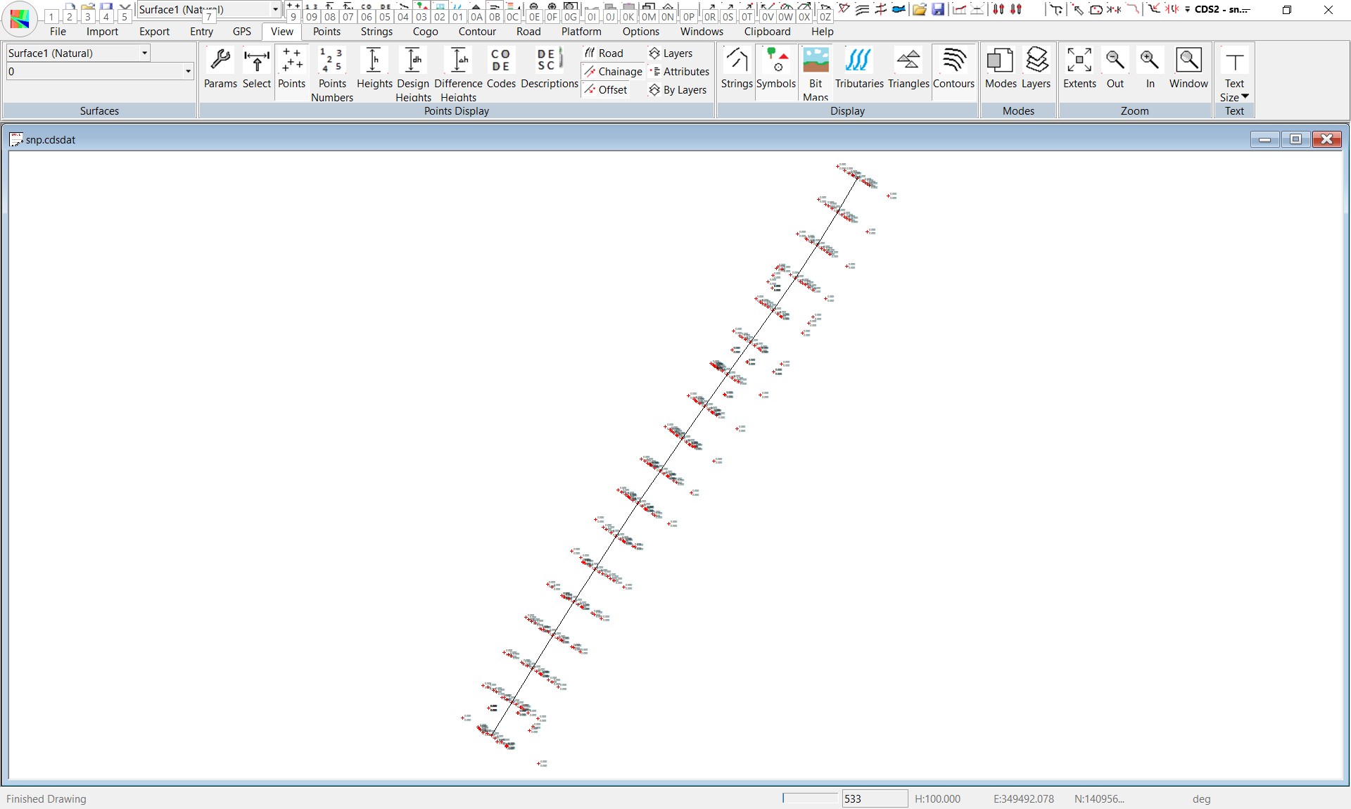
Start CDS, and use File, Open to bring up Job SNP which has been provided in the Foresoft tutor Folder..
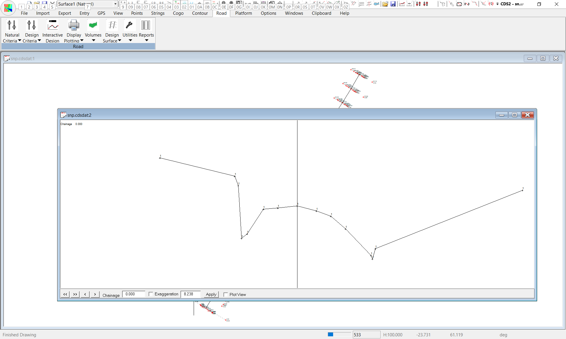
Close whatever Job you had up before, and Maximise the window so you can see a screen similar to that below.
As you can see we have a series of points which are approximately perpendicular to the string down the centre, and it is clear that they are meant to be cross sections.
Now that you are familiar with the layout of the job, we can start on the process of getting the points shown in plan view to appear in profile and section.
Calculate Chainage & Offset from Coordinates.
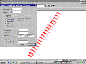
This routine is a Road Utility, so select the Road option on the menu bar and highlight Utilities and select the option to Calculate Chainage and Offset from Coordinates.
However, it is important that you know both methods, since some jobs will have strings which are not as easily ‘picked’ as the one in this example. Next you need to decide which points to calculate chainages and offsets for, and if this case we need All points, so select the Radio Button adjacent to All.
The offset of the String is zero since the string we are using is the centreline, so no action is needed in this case.
Likewise, our start chainage is zero, so we can move past that field.
You will see the Offset Limits have large numbers both left and right and in this case they are appropriate.
The offset limit is used in determining which points in a database belong to which road, or in the case of a road which twists and turns and doubles back on itself, it can determine which is the correct chainage.
Basically, if you know that the field party did not collect a point any more than 30 metres from the centreline, you can set a negative and positive value of 30, and only points which fall within that longitudinal envelope will be allocated to the road.
You will now see the Check Box for Allocate Road Number, and you should select it so a tick appears, and enter a value of 1 into the field to put all these points on Road 1.
The purpose of road numbers is to allow you to have different sets of profiles and sections in the one job, such as when you have two roads intersecting. All the points can appear on the plan, but you need to differentiate which points belong to which road when you come to plot profiles and sections.
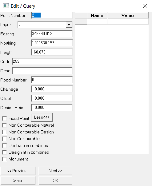
Once all these fields have been completed as described, you should select the OK button, and you will see the “Please Wait” bar flash as the calculations take place, and you will now be returned to the Road Window. At this stage it is wise to check that things have worked, so do a Query on Point 2 by pressing the ‘?’. You will see that is now has values for chainage and offset and it is on Road 1. You can use the Next and Previous buttons to check on other points if you wish.If you Press Z for zoom, followed by E for Extents, you will now see points appear within the roadworks window as seen at left.
This means we have the makings of a road as all the points now have some chainages and offsets, along with a common road number.
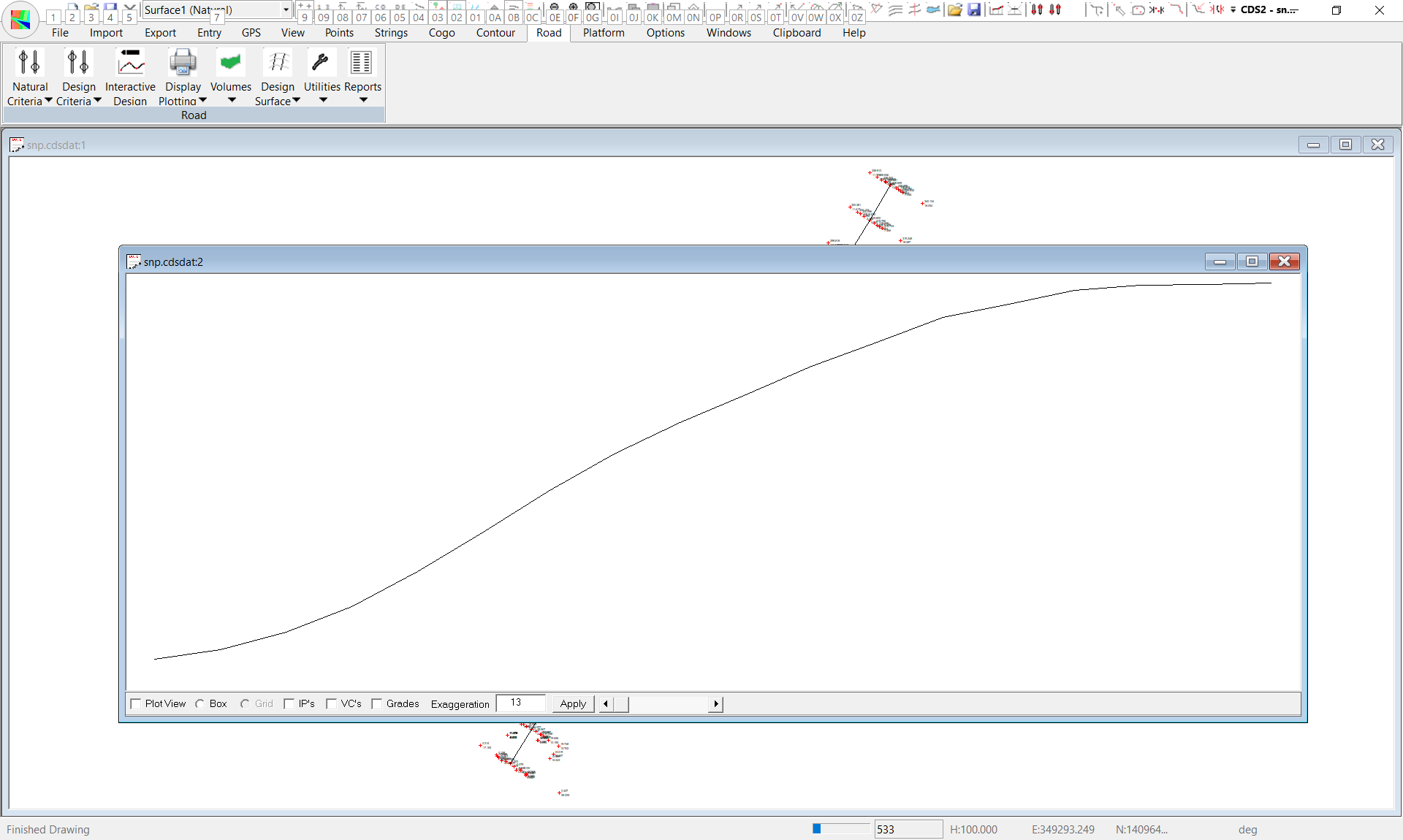
You now wish to see a profile, so pull down the Road Menu, highlight Display and Plotting and Select Display Profile.
Click on the "Road Works Parameters" icon and tick the "Use Road Numbers" radio button to tell CDS we are using points in the database and not interpolated data from a string. Make sure Lie1 is ticked and we are using Road Number 1.
Close down the cross section window since it is no use at the moment, and we will find out where the sections are.
If you use the “?” key to Query the points in the database, and then use the Next button to move through some of the points while concentrating on the Chainage field, you will see that no two chainages are the same. While you will see values of 0.000, and 0.006 and -0.032 and 0.057 and the like, you will see that these values do not, as they stand, make of a cross section of chainage 0.000, because computers live in an artificial world where things are meant to be perfect.
However, we carry out surveys in the real world, where we intended all those values to appear on the cross section at 0.000, and the fact that the pole was a few centimetres off perfect square is well within the acceptable tolerances of this type of work.
Since it is not possible, nor required, to locate the points on the cross section to millimetre accuracy, we now need to run another routine which tells the program what allowance we are prepared to make for the natural wanderings of the chainman as she walks across the section.
We do this by applying a Chainage Filter (Snap in previous versions).
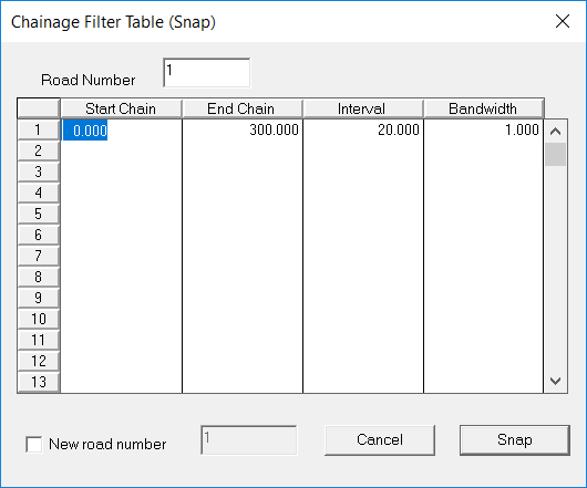
If you pull down the Road menu, highlight Natural Criteria, and Select Chainage Filter, as screen will appear as seen below.
Chainage Filter
The bandwidth is simply the distance from the exact chainage that you are prepared to allow as an acceptable amount, taking into consideration the field conditions.
In this case, we feel that the chainman should have been able to keep within 1 metre of square off, so enter 1.00 for a bandwidth.
Now select the Snap button, and the calculation will take place and return you to the road window.
Now pull down the Road menu again, highlight Display and Plotting and select Display Sections.
This time the section screen will appear with a display of the cross section at Chainage 0.00 as seen below.
Once there are two or more points with the same chainage, the program is happy to consider that they might be a valid section and display them for you. What is displayed will also be plotted when you come to plot out the sections, and this is not what we want.
If you take the trouble to continue reviewing the data, you will find there are more of these types of thing at 108.46 and 328.43 to name a couple.
What we need to do is to arrange for these items which are needed for detail information, and on the plan view, do not appear on our cross sections of Road 1.
You should pull down the Window menu and select Tile Roadworks.
Then ‘click’ your cursor in the Plan window to make it active since you will need to use the point editing facilities attached to the plan view.
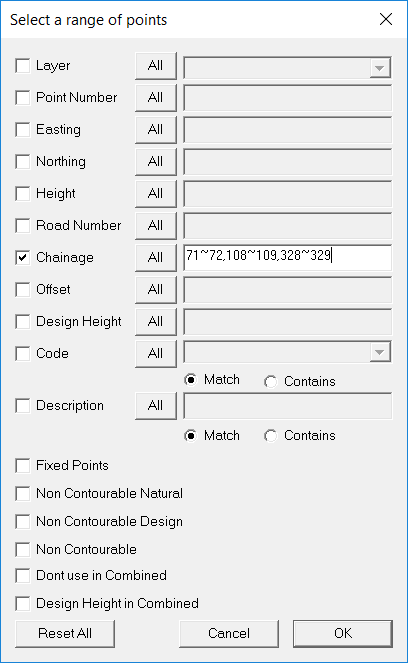
Pull down the Points menu, highlight Select, and choose Select by Range.
While you could choose any number, it is good practice to get into the habit of using one particular Road Number for the storage of points that you do not wish to appear on the profiles and sections.
You may wish to choose a road number of 99, or if you feel that a road number of 88 might bring good fortune, use it instead. Once you select OK, the road number of the offending points will be altered so that they will no longer interfere with your plotting of sections, and you can now use the techniques from Tutorial 5 to set up plot parameters, and plot out a profile and sections if you wish.
|