| < Previous page | Next page > |
|
Stockpile Volumes
In this tutorial you will learn how to ;
* Use Volumes, To A Plane to calculate a stockpile volume.
* Use different surfaces within the one job.
* Calculate volumes between different surfaces in the one job.
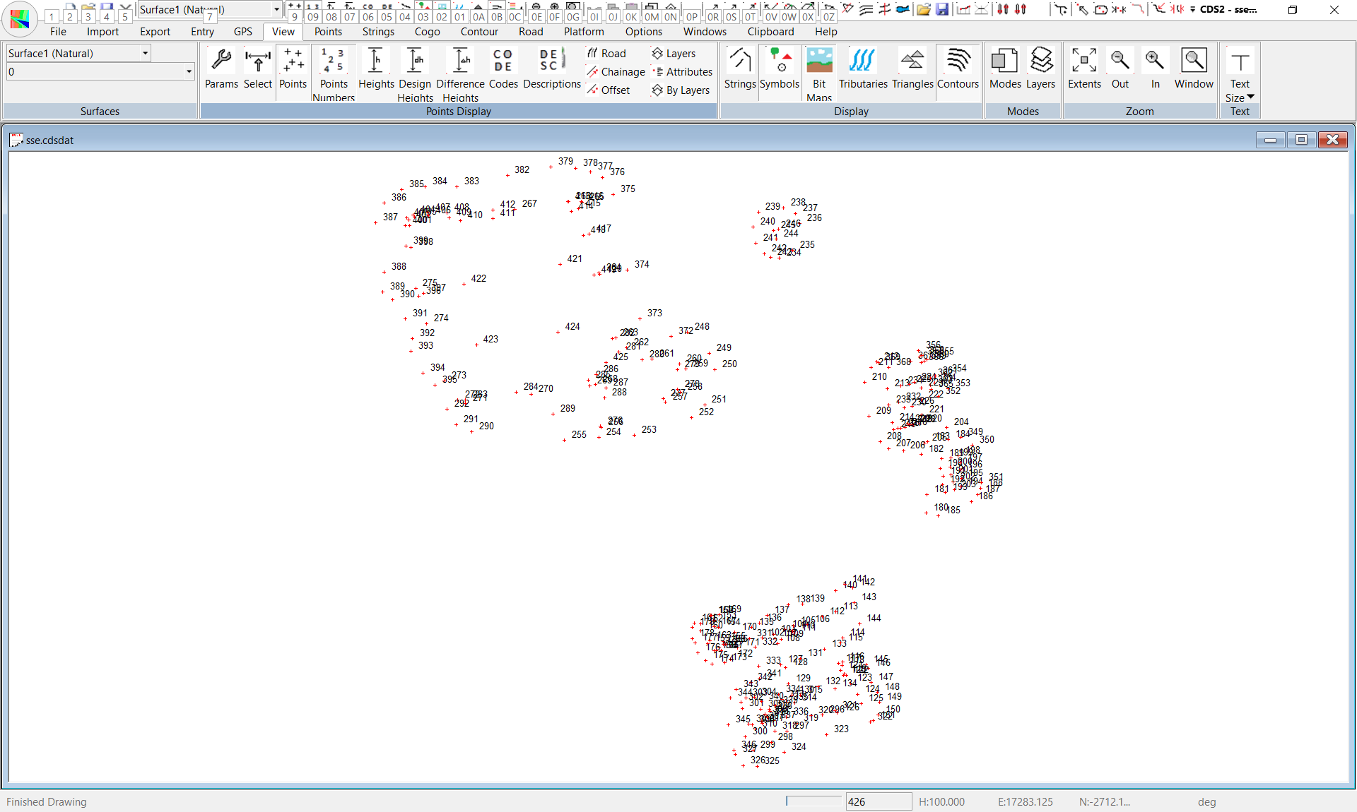
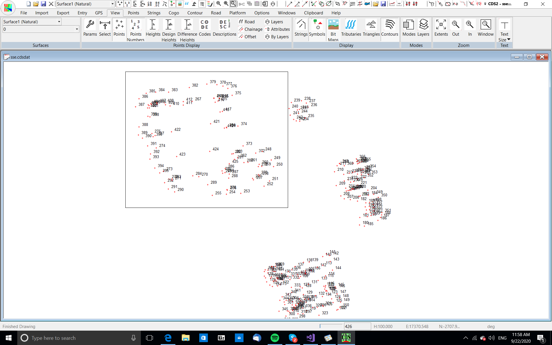
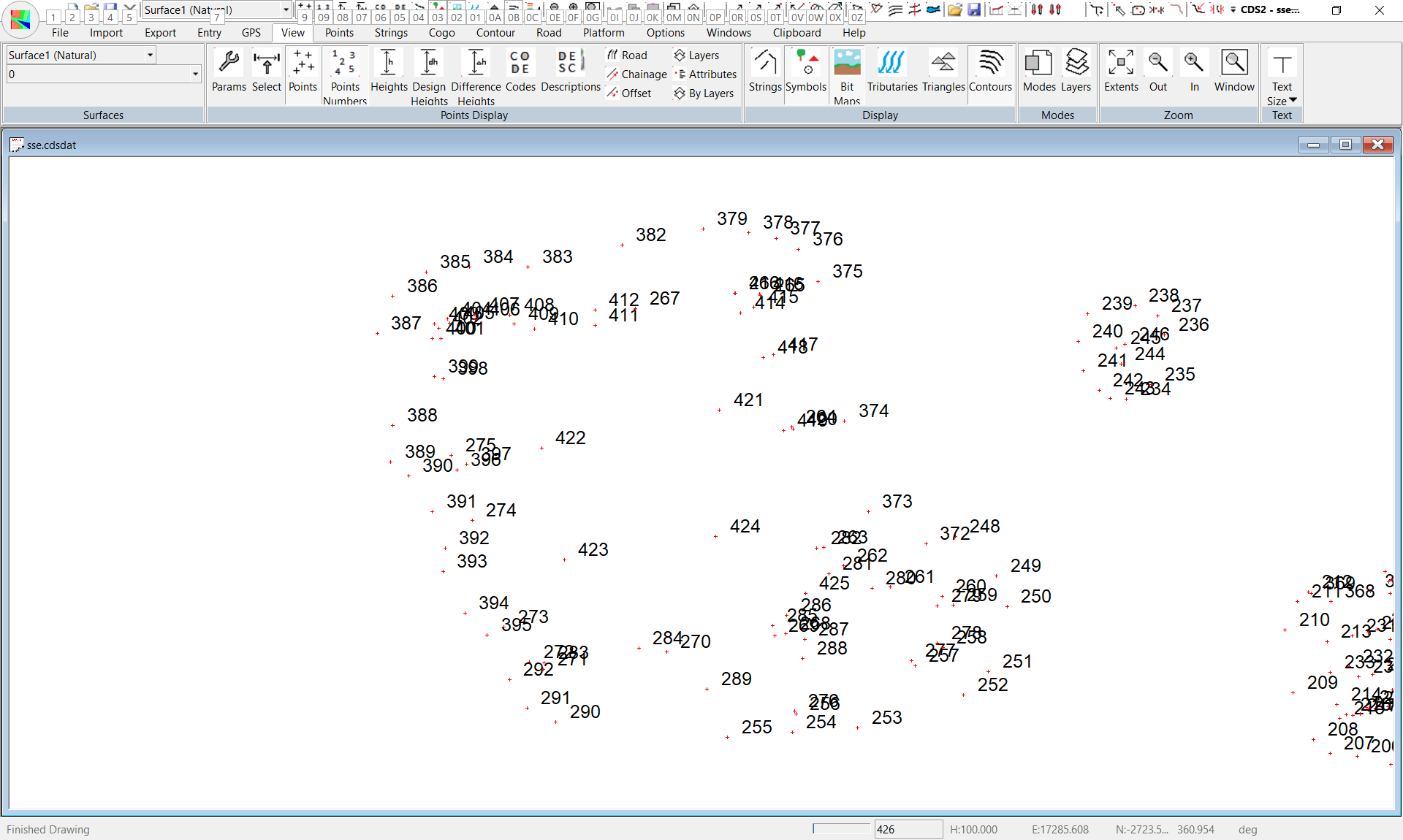
To see the data more clearly, you should use Zoom, by either pressing Z, or by selecting the Zoom Icon, and you should select a window similar to that seen in the screen below left to get a screen similar to that below right.
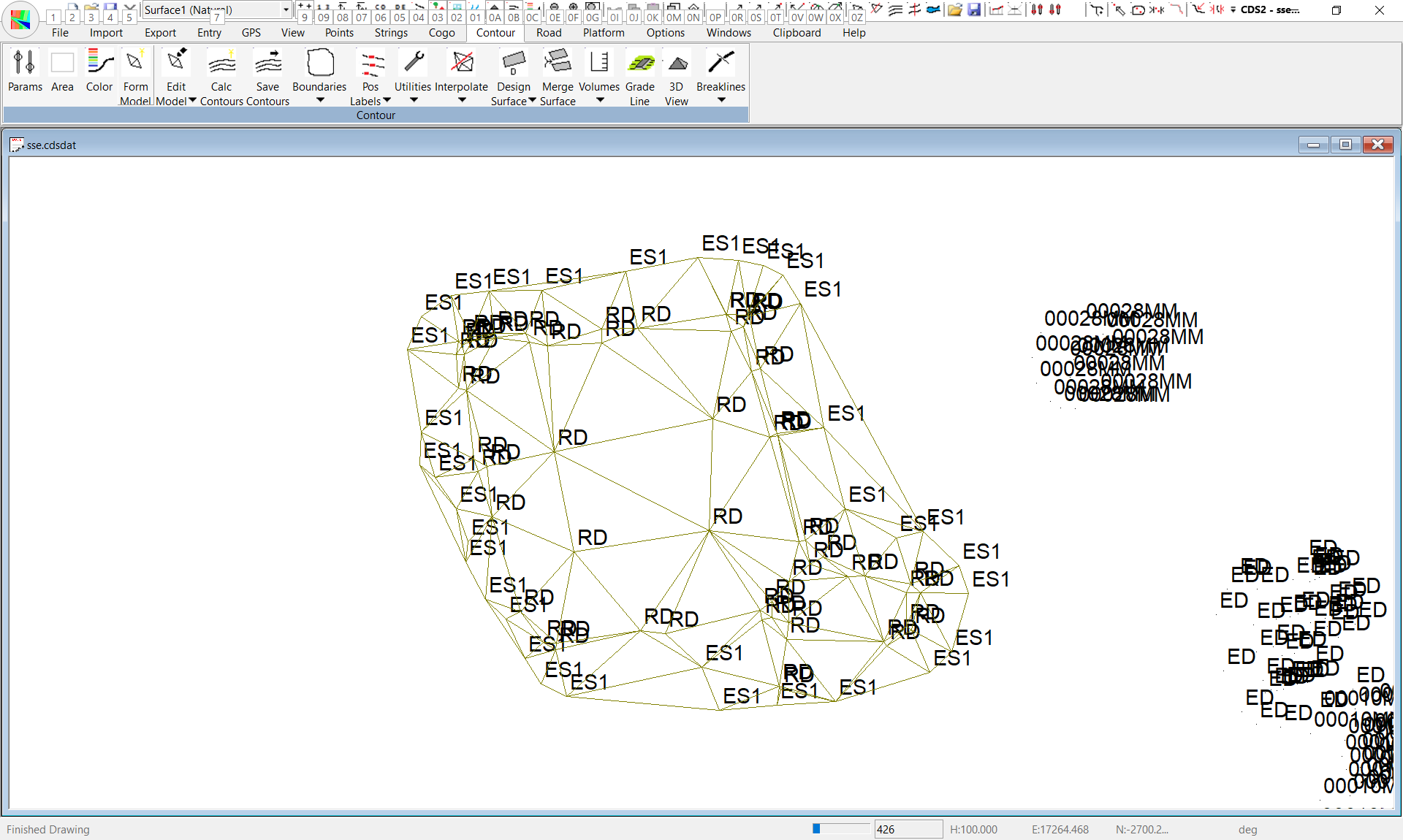
There is not a lot which you can determine from the point numbers, however the field party has coded all of the points, so you should turn the codes on to see if they provide any guide to what we have.
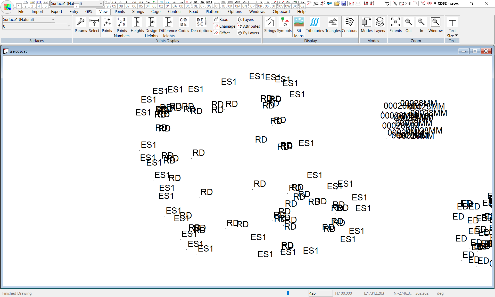
Select the Layers icon, and set it to display the code, and the following screen will appear.
You can now see that the field party has coded all the shots on the edge of the first pile with a code of 'ES1', and the actual material in the pile is coded 'RD' to indicate it is general road material.
Before we can calculate how much material is in the pile, we must first determine the base on which it is sitting.
In Tutorial 7, you had the luxury of being able to actually do a survey of the base before the material was dumped, but this has not occurred in this situation. So, the only thing we can do here is to assume that there is a base surface that is made up of all the points that are on the edge of the stockpile i.e. the points coded 'ES1'
Pull down the Contour menu and select Surface Parameters.
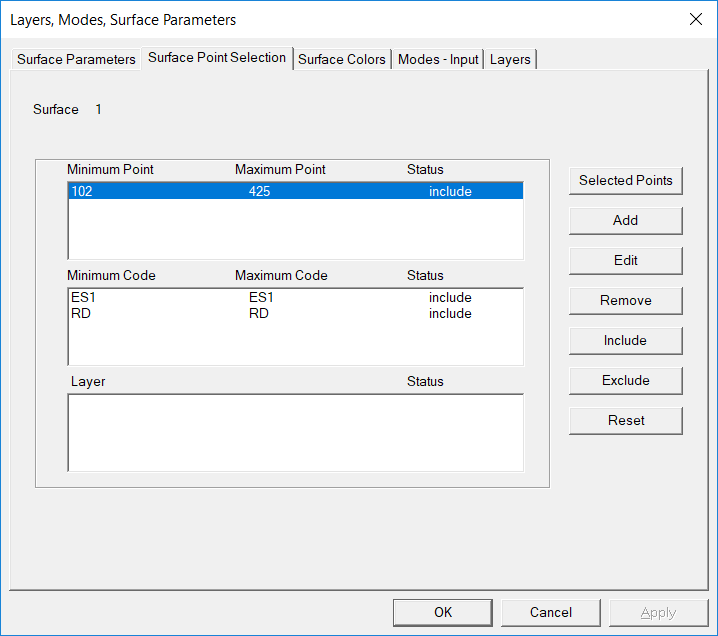
If you now select the tab which is titled Surface Point Selection the screen will appear as seen below.

You will see that there are three distinct areas which will allow you to determine the points to be used by the Point Number, their Code, or their Layer.
In this case layers were not used, and the point numbers are scattered, but the codes will allow us to select efficiently.
Select the existing code range with your cursor, and then select the Edit button.
A box will pop up to with fields for the Minimum and Maximum codes you wish to use.
In this case you should enter 'ES1' in both fields and then select OK.
Now select OK to close down the Surface Point Selection window and return to the main screen.
Now pull down the Contour menu and select Form Model.
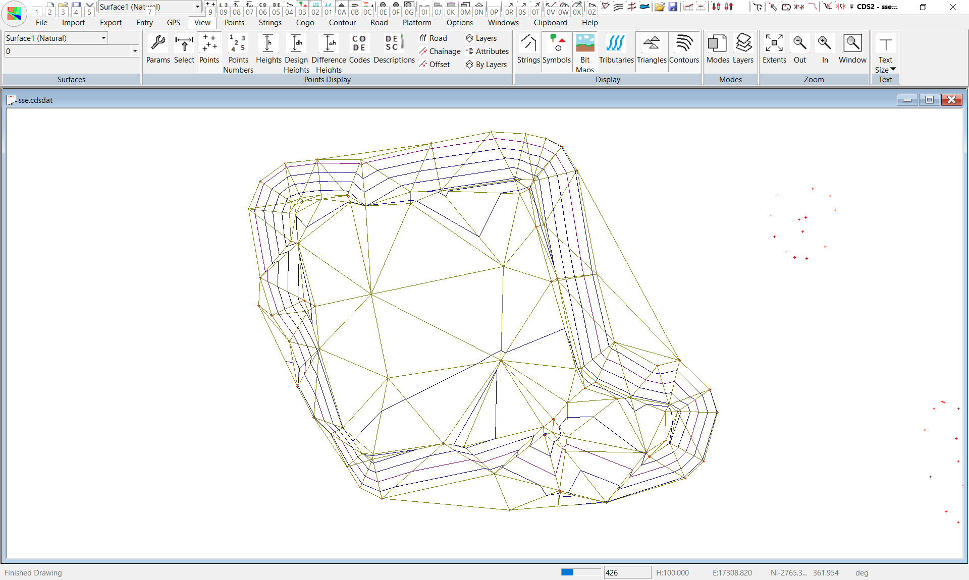
The screen should appear as below, and you will see that the triangles have been formed across the base of the stockpile, which is what we intended.
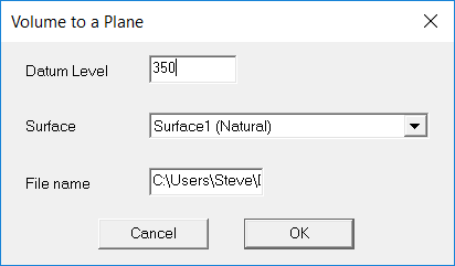
We now wish to determine the volume between this surface and an arbitrary datum plane below it, so pull down the Contour menu, select the Volume option, and select the option "To a Plane'.
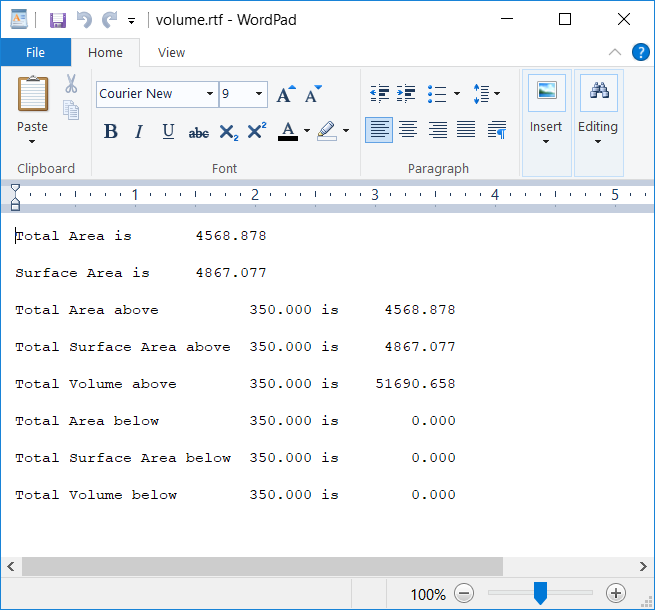
The screen shown below left will appear, and you should fill in a value of the plane of 350, then click OK, and the results will be displayed in Wordpad, as seen in the screen below right.
You should make a note of the area of 4625.812 square metres, and the volume of 40436.019 cubic metres, or you may print it out if you wish.
Now you need to model the whole of the pile, and determine the volume above the same plane, so pull down the Contour menu, and select Surface Parameters, then select the Surface Point Selection Tab as before.
Now select the code range, and then click on the Add button.
When the pop up box appears, enter the Code 'RD' in both fields and press OK.
Your screen should appear as seen below, indicating the surface you want is the one that has points with Code 'ES1' and points with Code 'RD'.
Close the Surface Point Selection screen by selecting OK.
Now pull down the Contour menu and select Form Model.
The screen should appear as below, and this time you can see that the model includes all of the points in the first stockpile.
NOTE : when you use this, or any other method of calculating volumes with your own data, it is important that you understand that the contours formed must accurately represent the surfaces you are using, otherwise the volumes you produce will NOT be accurate.
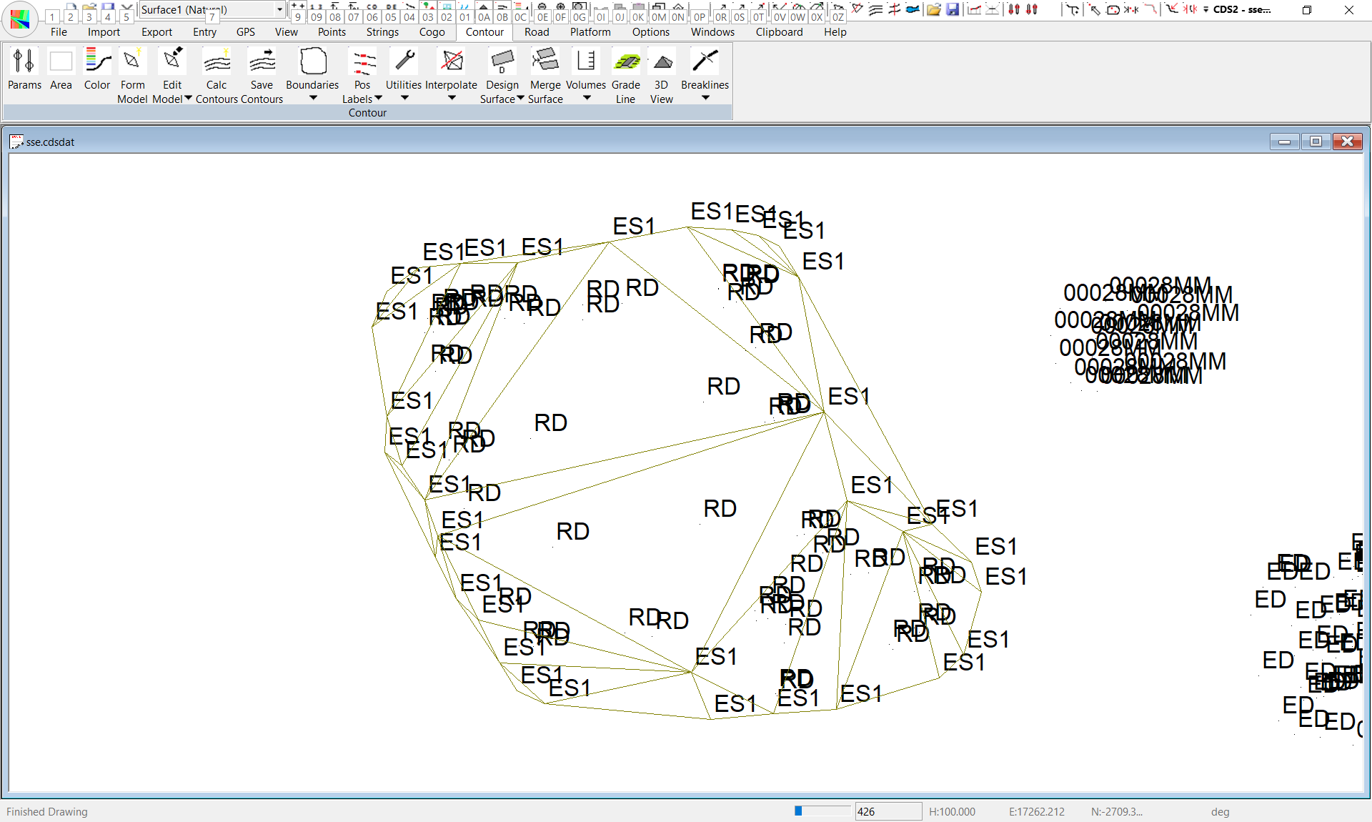
So, here you should now Calculate Contours and allow them to be saved, and the screen should appear as at right.
Since you did not do the job. it is difficult to know whether these contours are correct or not, but if your screen appears the same as the one at right you have got it right.
There is a small disturbance to the wall of the pile at about the 5 o'clock mark, and that is quite correct as a loader had been taking material from that area before the survey was done.
Now that you have the surface accurately modelled, you should calculate the volume to the plane, so pull down Contour, select Volumes, and To a Plane, and enter the value of 350 for the plane.
The screen should appear as below, with the answers displayed in Wordpad.
The first thing you should do is check the figure presented for Total Area. If it is not the same as the value you calculated when you did the base surface, something has gone wrong, and you are not projecting the same areas onto the plane.
In this case, the areas agree, so the volume of 52171.391 can be used.
If you now subtract the volume of the base, of 40436.019 from this figure you will get the amount of material that is in the pile.
Be careful when presenting these figures to a client, and don't get carried away and specify a volume such as this to three decimal places, because it is simply not physically possible to locate the pile to that sort of accuracy in the field.
So, in this instance a value of 11,735 cubic metres is more than accurate enough, and it is probably arguable that it is gilding the lily a little to specify down to the last 5 cubic meters over an area of this size.
And yes I know that your client will argue that you need to report every cubic spoonful to minimise the amount payable if the principal briefs you, or to maximise it if you work for the contractor. You need to carefully consider your own professional integrity, and be wary of being drawn into wasteful arguments over trivial differences in volumes which are simply not measurable under normal field conditions.
When an argument arises over quantities, it is recommended that first you take a simple "reality check" to see how accurately they were, or could have been measured in the first place. If the amount being argued over falls within the normal 'error ellipse' for work of this kind you might consider whether you should advise the warring parties to split the difference and get on with something constructive.
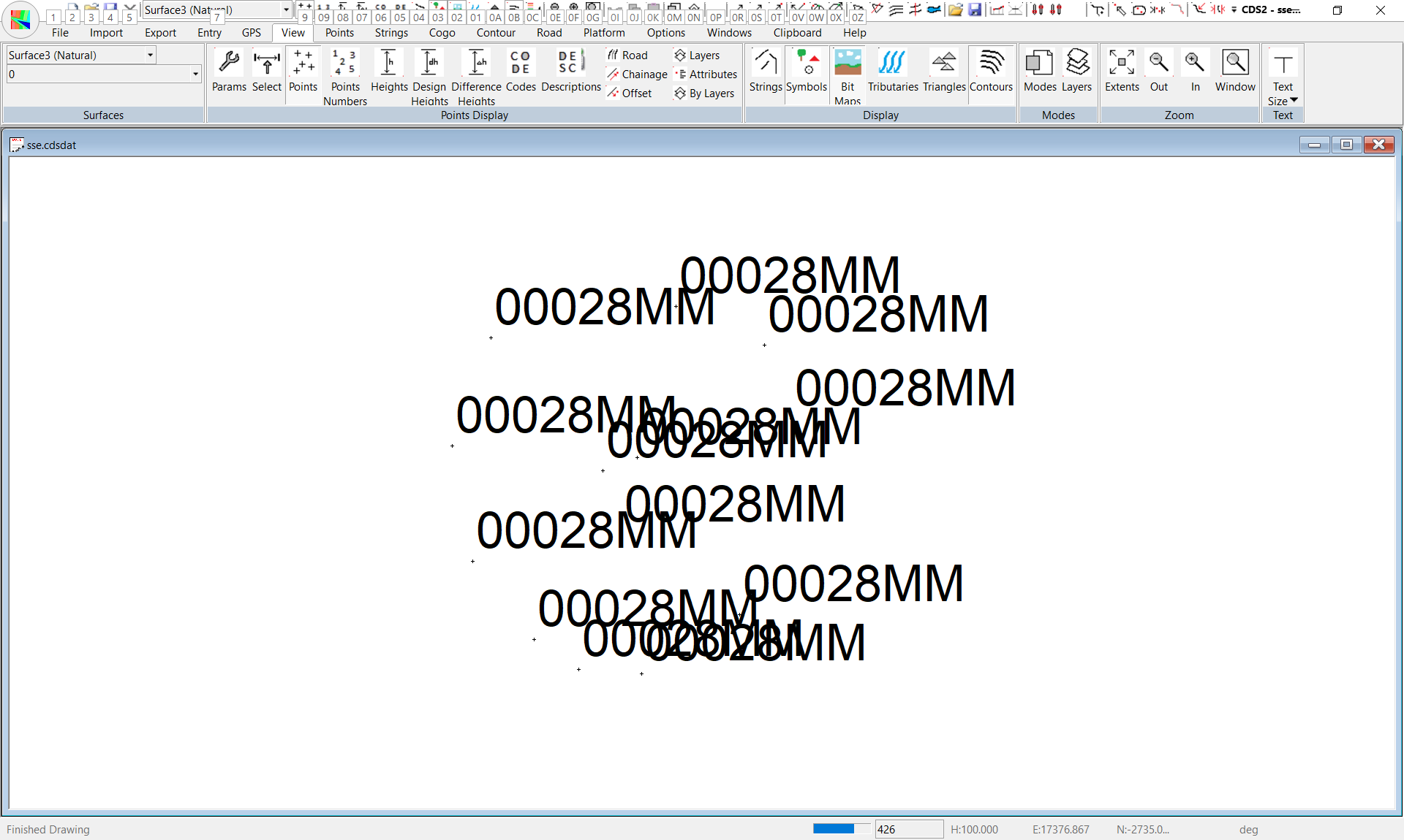
If you now Zoom Out and examine your data, you will see the pile at the bottom of the area has the edge points coded as 'ES2' and the material itself coded as '20mm' indicating 20 millimetre screened blue metal, and if you wish you can substitute these values in the procedure above and obtain a volume, but we will do it by an alternative means.
Using Different Surfaces
With CDS you now have the capability of assigning different sets of points to different surface within the same job, and we will use this facility now to set up the base of stockpile 2 as Surface 2, and the whole of stockpile 3 as Surface 3.
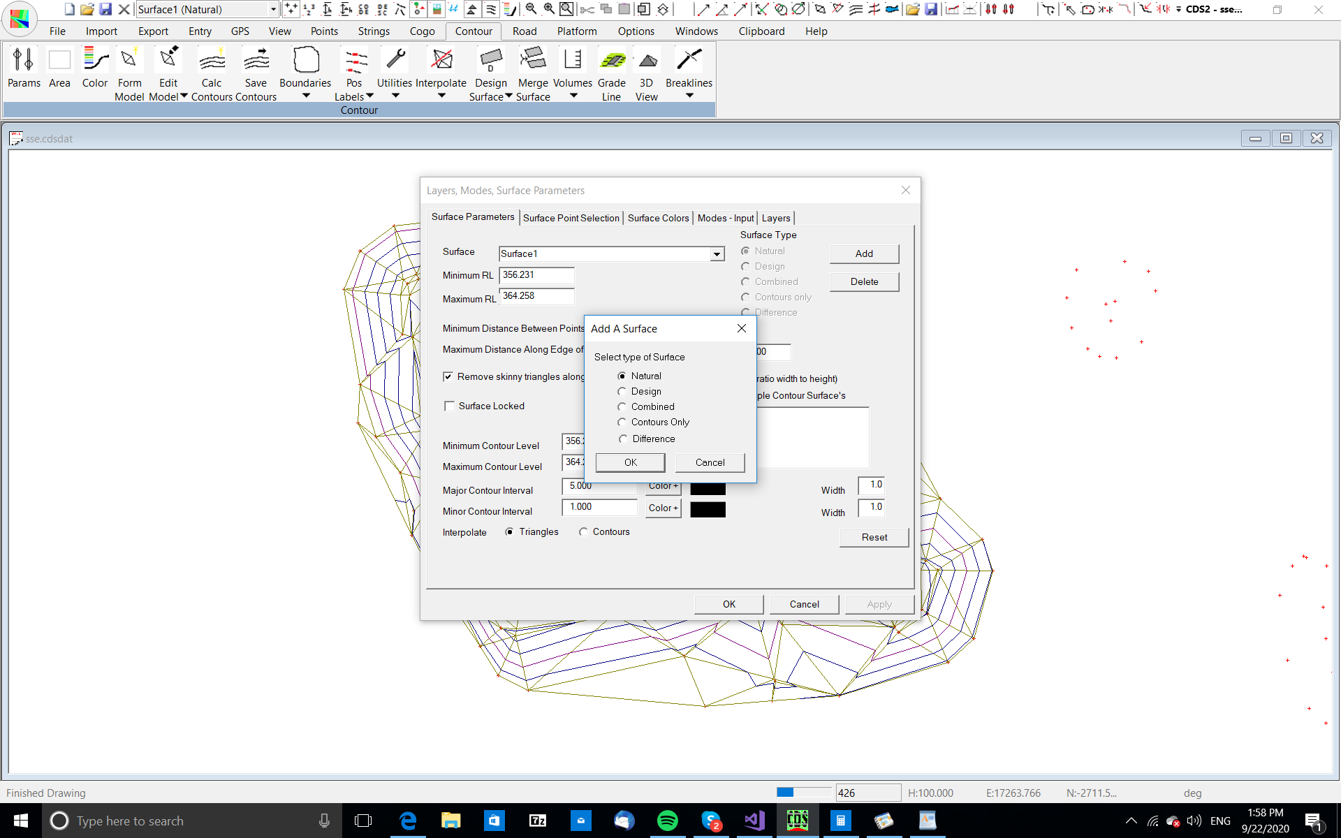
Pull down the Contour menu and select Surface Parameters.
If you look to the right at the top of the screen you will see a button titled Add, and you should select it.
The following screen will appear.
Press OK, and this will save away Surface 2 as the base of the second stockpile.
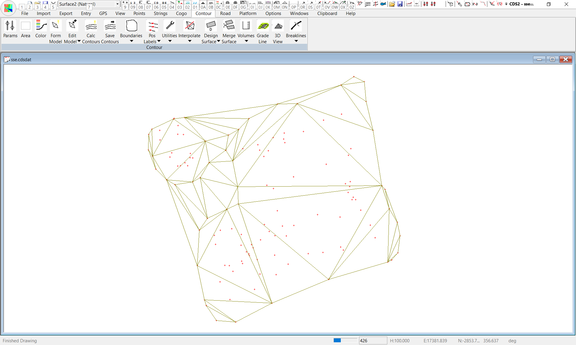
Check that Surface 2 is selected on the Surface Parameters screen, and when it is, close the screen.
Now zoom extents so you can see the whole job, and Zoom a window around the stockpile at the bottom of the screen.
Now that you have separate surfaces defining the base and the entirety of the stockpile, you can determine the volume in this pile by using the Surface to Surface method.
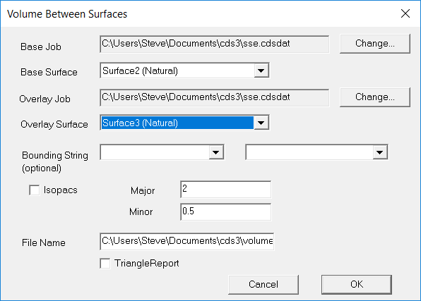
Pull down the Contour menu and select Volumes, followed by Surface to Surface.
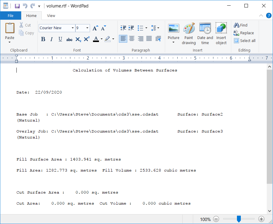
When the screen appears, you need to change the Base Surface to be Surface 2 and the Overlay Surface to be Surface 3, so your screen will be similar to that at right.
Now you should select the OK button, and the volumes will be calculated and the answers displayed in Wordpad as seen below.
From these results you would report that there is 2530 cubic metres of 20 millimetre blue metal available in the yard.
If you now Zoom extents, and then Zoom a window around the small pile immediately to the right of the first pile we calculated, you will see a screen similar to that at right.
Now select the Surface Point Selection screen, and set it to Surface 4.
You need to specify a Point range from 234 to 243 for this surface.
Save the parameters and form the model for Surface 4.
Now select the Surface Point Selection screen again, and set it to Surface 5. Specify a range of points from 234 to 246 and save it away.
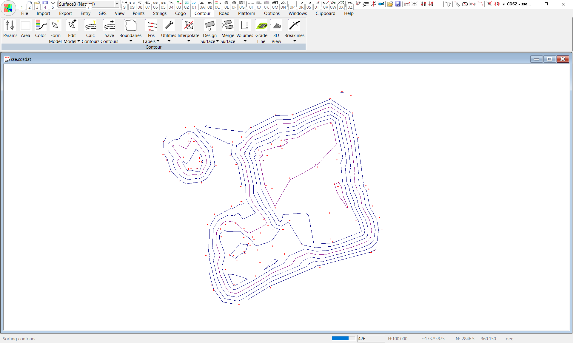
Make sure Surface 5 is selected in the Surface Parameters screen, and then form the model, and calculate and save the contours.
You should get a result similar to that shown below.
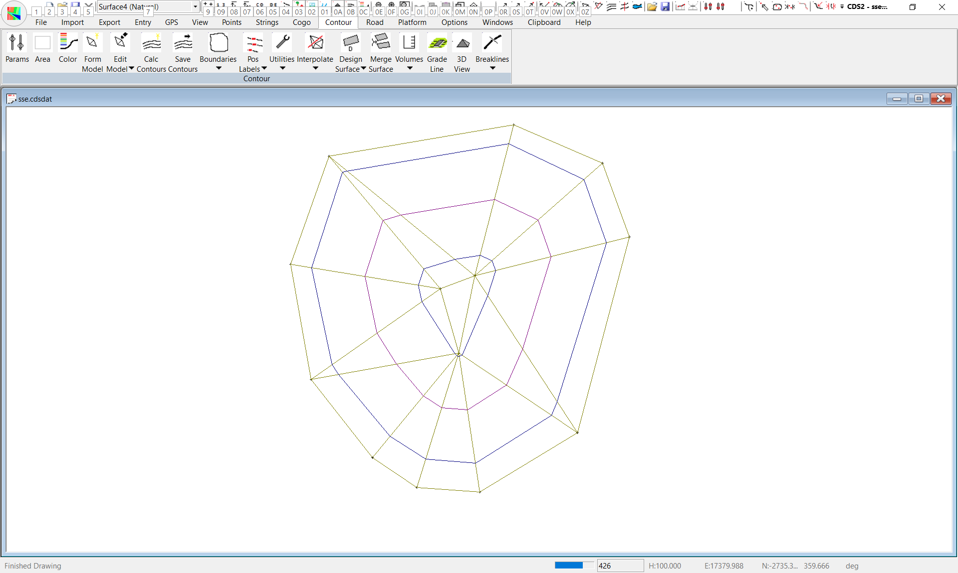
If you do, and you then calculate the volumes between Surface 4 and Surface 5, you should come up with an answer of around 126 cubic metres.
Note that once you have modelled and contoured the various surfaces, you can get them back on the screen simply by selecting the surface you wish to see on the Surface Parameters screen.
There is no need to re-model or re-contour.
|