| < Previous page | Next page > |
|
Head Up Digitizing with CDS
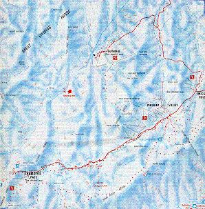
In this tutorial / white paper we are going to show how to perform on screen digitizing. This involves scanning or photographing the plan, photo or map. Converting this scan into a bitmap file. Telling CDS to display this bitmap as a background image and geo-referencing the map so it appears at the correct size and scale. We will then discuss inputting any relevant points, contours or strings.
In the example given we have a contoured map. We wish to create a digital terrain model from the map contours. From the terrain model we are going one step further and show how we can drape the background bitmap on top of the triangles and create a 3D map.
Scanning the plan
We suggest you use a flat bed scanner. It is possible to use a digital camera but you may introduce distortion in the bitmap. At present CDS has no facilities for ortho-rectification of the bitmap. Ortho-rectification is the process where any distortions introduced by digital photography are corrected in the bitmap. It is on our list of things to do however.
Geo-referencing in CDS
Next step is to reference the bitmap so that the bitmap is scaled to real world coordinates. For example UTM or something. In this example we are happy with coordinates at real size but we are happy to call the lower left of the drawing at 0,0 as a convenient reference point.
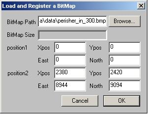
From CDS we first wish to create a new job. From the file menu click on New and enter in a job name of perisher300. A blank view will appear as we firstly have nothing to display. The menu items for bitmap display are found in the Options menu. From the options menu click on "Set Background Bitmap". The following dialog is displayed.
In this example we wish the 0,0 position to be referenced to a world position of 0.0 and 0.0. We wish to calculate the real world coordinates of the top right corner of the bitmap. We know that we scanned the map at a resolution of 300 dpi and that the map scale was 1 to 50000. Thus the far right easting is calculated as follows.
The max bitmap is 8944. But we have 300 dpi. Therefore there are 8944/300 . In this example we are converting to metric. There is 22.54 mm to the inch. ie 8944/300*22.54 mm. But scale is 50000. Therefore multiply by 50000 and divide by 1000 to convert from mm to metres. ie value of 8944 and 9094 as shown in dialog above.
To view the bitmap now use the Z (zoom ) E (extent) command to view the bitmap. Please note that the dynamic zoom and pan works with the bitmap. I find it more convenient to navigate bitmaps using these functions than in Paint for example. You can also use the Join command to measure distances on-screen and also be aware that the surround option is ideal for measuring area's on screen. Please be aware however that any distances and areas are only as accurate as the geo-referencing. We suggest that you use the join command to measure two known distances onscreen and compare the values with there real life values.
Digitizing
In the example given we wish to digitize in some heights using contours shown on the map. Please be aware that more and more data is now available for download from satellites etc. It could save you some time. However in this example this is the only height data we have so we wish to digitize in the contours.
All the existing data entry methods are still available. For example the add points function will still operate and you can click on a point and fill in any extra data such as point codes, heights, chainages etc as you go. In digitizing mode however we are normally less rigorous and we are more than happy to trace a line or contour on-screen and have CDS automatically enter the data.
We have added in a new mode (digitizing mode). When in this mode the most commonly used items are displayed on the right menu. The things you would most often use are the option to set the minimum distance between inputted points, ability to specify heights , codes etc when inputting data. Also the options for adding points and adding strings are also handy.
To enter digitizing mode click on the "Options" menu and select the "On Screen Digitizing" menu item. Before entering any points it is worthwhile specifying a minimum distance between points. This allows us to move cursor around the screen with the left mouse depressed and not pick up 10 million points. For this job we wish to set this distance to 100 meters. Right click the mouse and select the "Tolerance" menu item and enter in 100.0
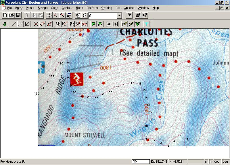
We are now ready to digitize in some contours. One additional thing though. We want to be able to sketch along the contour and have all the points go in at a constant height. We have zoomed in at the bottom left and we wish to digitize points in along the 1900 meter contour. From the right mouse button menu select the "Modes Input" option. In the "Prompt for Height" section set the radio button to Constant and set a value of 1900. We are now ready to digitize in the contour. We first need to tell CDS that we are inputting some data. From the "Points" menu select "Add Points". Select the start of the 1900 contour. Move the mouse along it keeping the left button depressed. Points at height 1900 are entered automatically. We have the following screen shot.
If you need to follow the contour off screen simply use the dynamic pan. Hold the middle wheel mouse down and drag picture until we have the rest of the contour. If you prefer to digitize an area at a time you may need to change the constant height set in modes. Right click select modes and change the height. Continue across the plan digitizing as much detail as necessary. I would suggest backing up at some predetermined interval.
I have completed the job for you and suggest that you download the cab file perisher300.cab from our site ftp.forsoft.com if you wish to view it.
Draped Bitmap Image
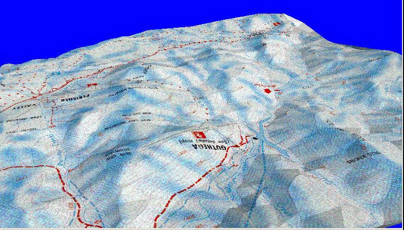
CDS now includes the ability to drape a bitmap image over a Digital Terrain Model DTM. We will do this next. The first step is to triangulate the job. From the contour menu click on the "Form Tris" option to triangulate the job. We can now view the model in 3D. From the contour menu select 3D views. From right mouse button in 3D view select the Face option and then the "Overlay Bitmap" option. We now have the bitmap draped over the triangle surface. To make the Australian Snowfields look more like something from the Swiss Alps we have also added in some vertical exaggeration. From the right mouse button select View position and add in an exaggeration of 2.0.
You can now view the plan in 3D. When you have a view you would like saved click on the "Create Bitmap" menu item from the right mouse button. The view pops up in Paint and you can then save as a JPG or whatever. I have included two views.
First view is looking towards Perisher ski resort.
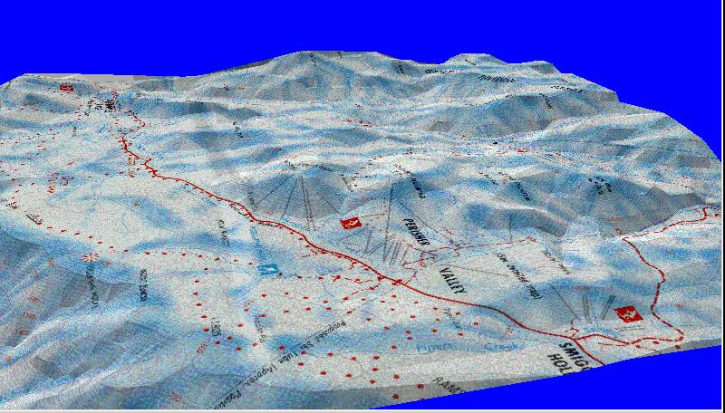
Second view is looking back down on Guthega with the ski field on the left and the dam on the right.
 We We |