| < Previous page | Next page > |
All Way design with stop bank and an outlet
Ezigrade has three types of grading designs. We have the traditional plane design, a constrained grade solution where the grading can vary between limits and what we call an AllWay design. This is a depression filling algorithm often used in the GIS community that makes all the water flow to the edge of the job. The procedure is to first pass a filter over the surface to smooth out hills and hollows etc and then a back filling algorithm is applied to fill in any ponding area's to a minimum grade. Unlike the constrained grade solution the back filling algorithm does not always result in a minimum solution. So it is possible that absolute volumes could be higher than a totally designed system. However the procedure is certainly less involved and it may be easier to take the computer generated solution.
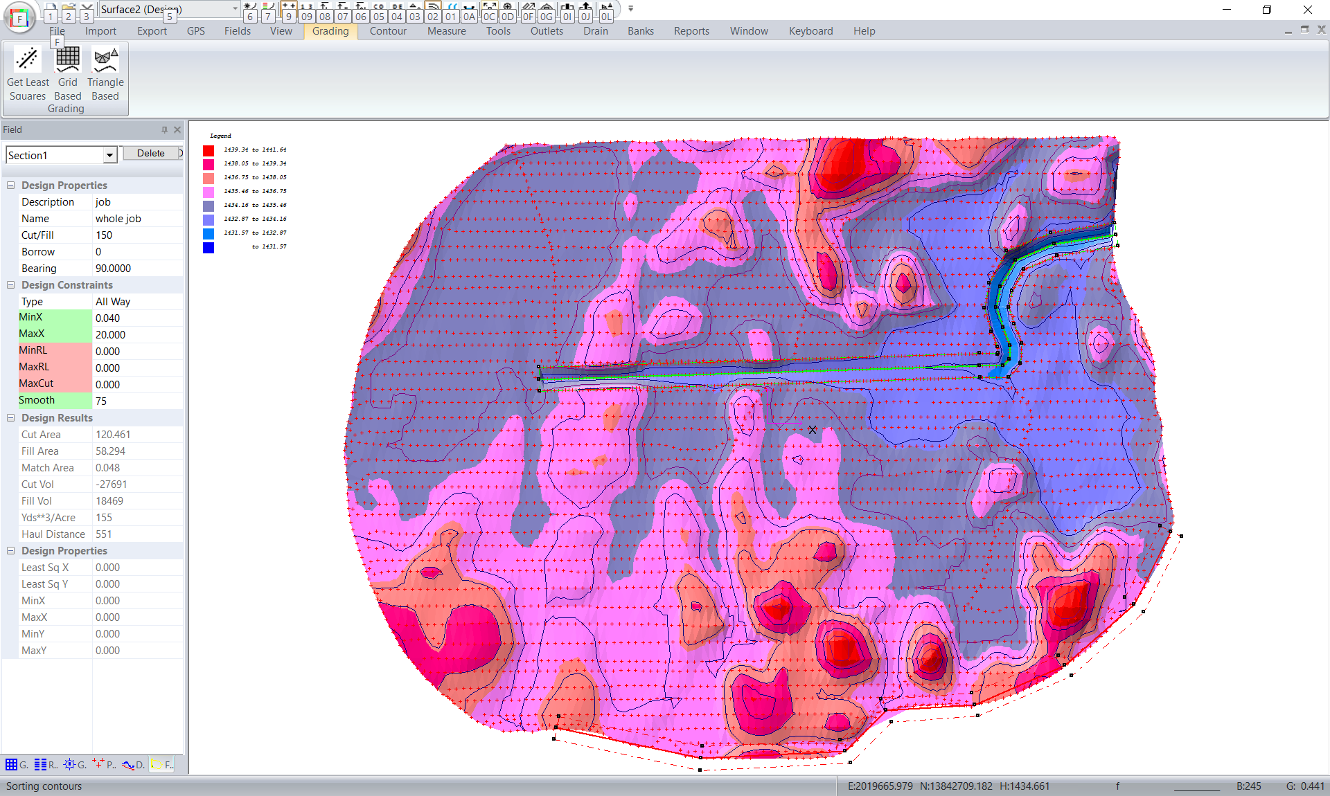
We have the following job:
You can see the low points and can envisage that after rainfall there would be quite extensive ponding.
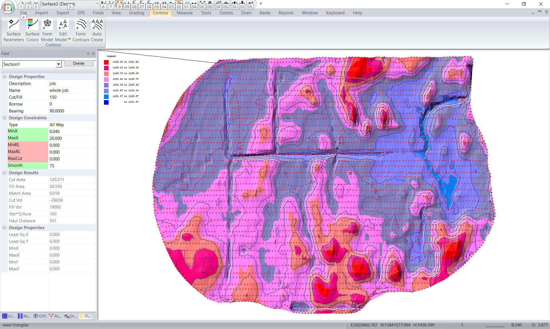
We have set the minimum grade to be 0.04% with a smoothing distance of 75 feet. If you set the minimum grade too high then you can tend to get a plane solution as it is physically impossible to get the grades to fit. We suggest that you try a solution with different values and see how the result works out. After running the solution we get the following:

You can see visually that the water will now exit the field appropriately. At the main exit point in the north east corner the algorithm has started with the existing height and all the low points upstream are back filled. The back filling algorithm never drops the height of a point but always adds to the height. After all the back filling is done the whole job is dropped slightly to still balance the cut and fill values.
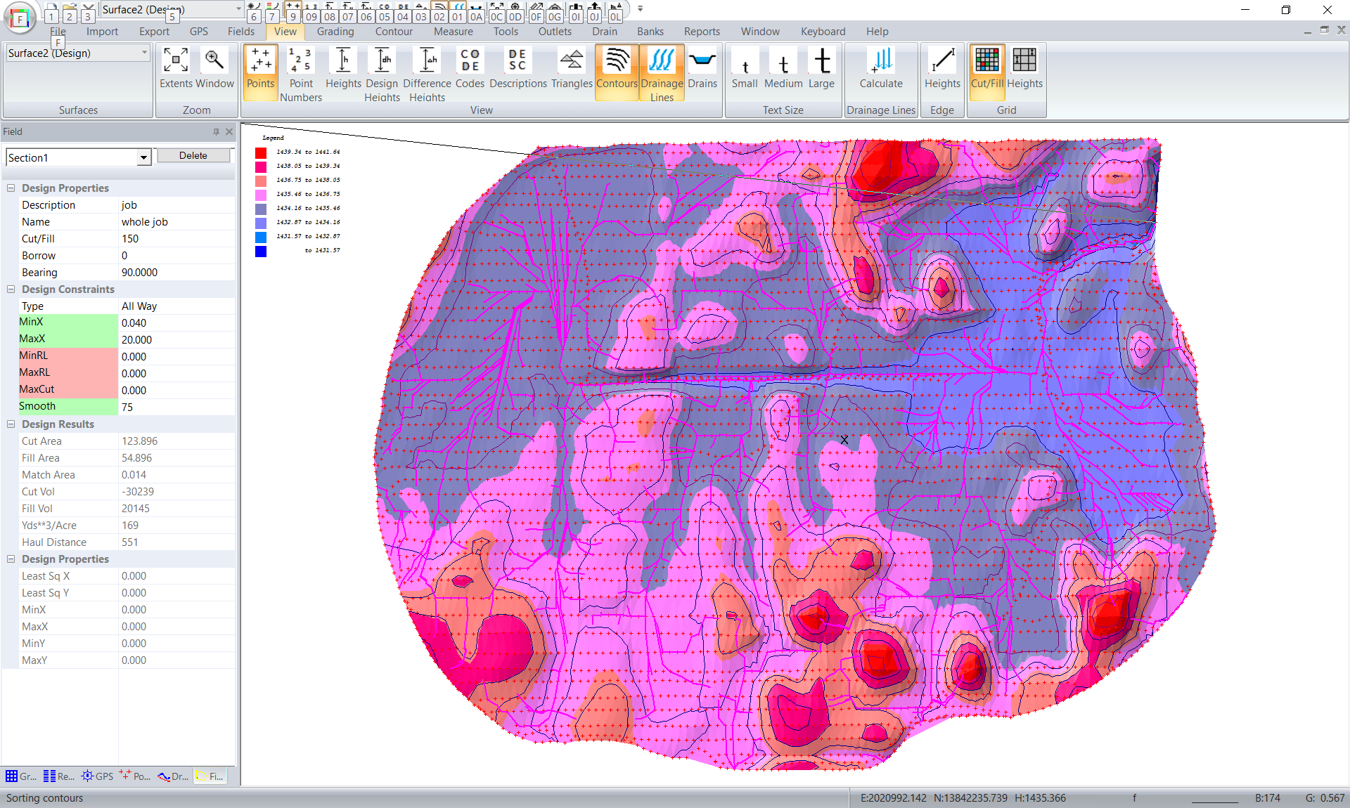
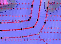
We have clicked on the View -> Drainage Lines and set it to 350 lines to get an idea of how the water flows. We can see that there is an area at the southern edge of the job where water flows out of the field.
In this example we want the water to flow out of the North East of the job. We have the option of using a "Stop Bank" in this area to avoid this. Click on Outlets -> InsertStop and click in a Bank so that it covers the edge of the triangles in this area. You move the mouse and left click, then move again and left click. Continue until you have entered all the points. Now hit the "Enter" key. If you wish to abort then hit the "Escape" key. After rerunning the triangle based grading we now have the following:
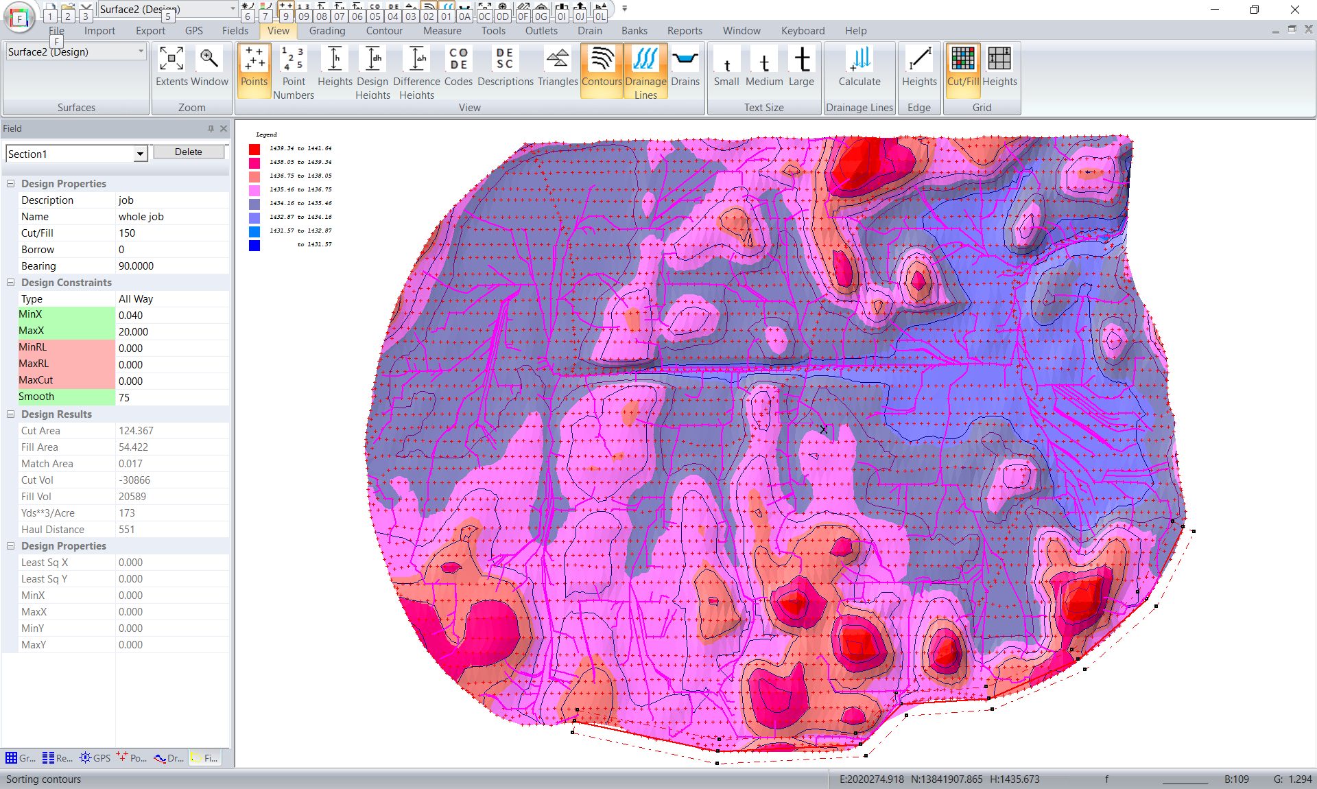
The water cannot exit this area of the perimeter now. However in some areas the water runs around the perimeter before dipping back into the center of the job; which mathematically keeps the water within the boundary.
We can still improve the earthworks if we can drop the height at the water outlet in the top north east of the job. To this end we are going to create an outlet that runs through the middle of the job where we can see the existing ditch. Go to the Outlet -> Insert Outlet. Start just outside the job and click in the alignment of the Outlet. ie Left click to start and then move mouse and left click again. Continue untill you are finished and then hit the Return key. You will then be asked for a width. Please enter 100 feet. I have left clicked on the Outlet so that it turns green so that we can see the result.
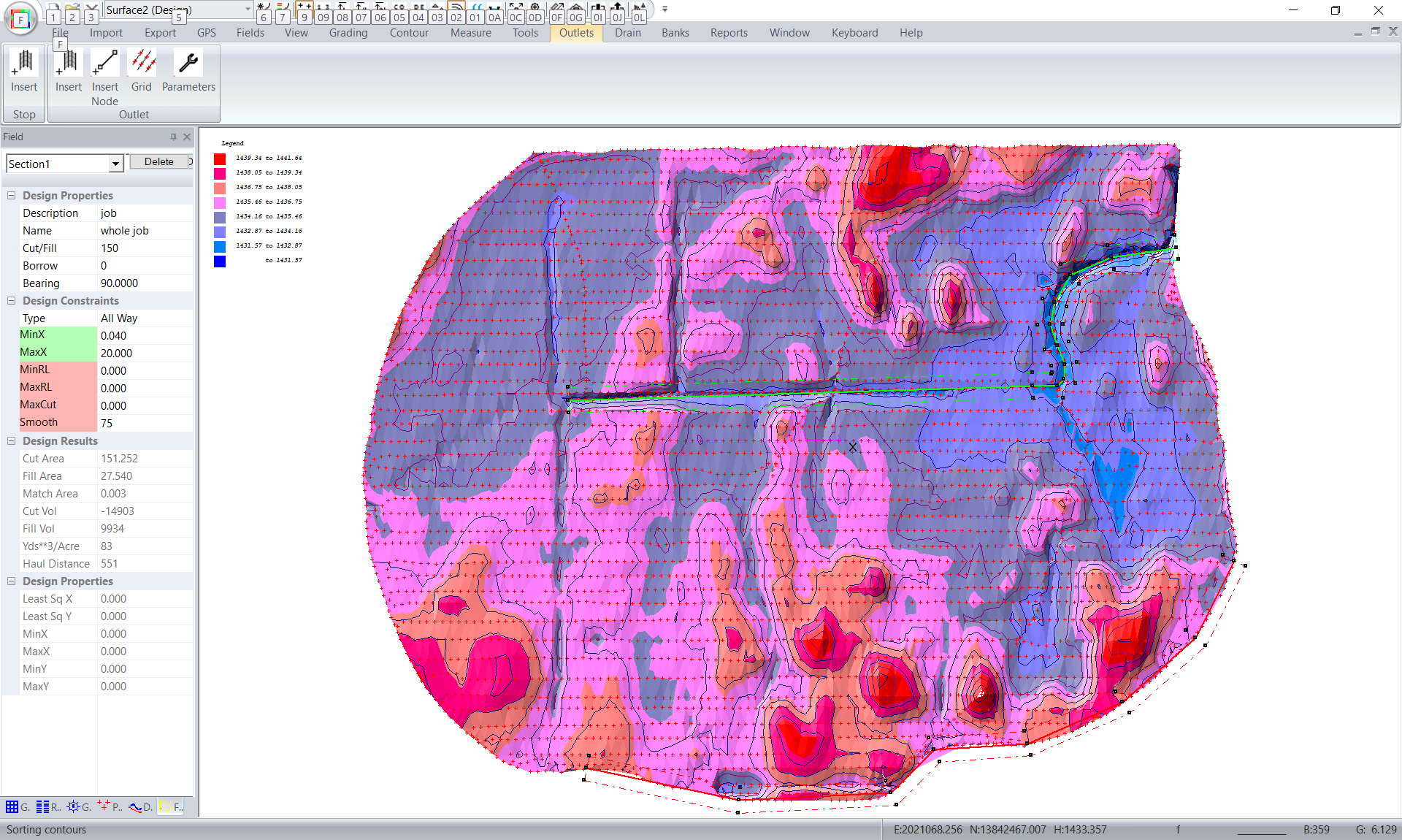
We now need to define the design parameters for the Outlet. Click on the "Parameters" menu item. I have added in the following. Please note that the grades are positive as we defined the Outlet from where the water flows out of the job to where it starts. Please be aware that the inlet can also be outside the job if it is to flow through the whole field.
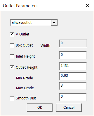
We have decided to use a V outlet . We also want to match the design surface. We have looked at the first iteration of the design and have set the Inlet height to 1434.965 You can run this and check this point later. For the water to run it is also good if the height along the outlet profile stays below any ponding area's. If not it is possible to end up with ponding areas on outside of the Outlet at these points. The minimum height is 1431.7 so we have entered 1431.0 Click OK to save the parameter values.
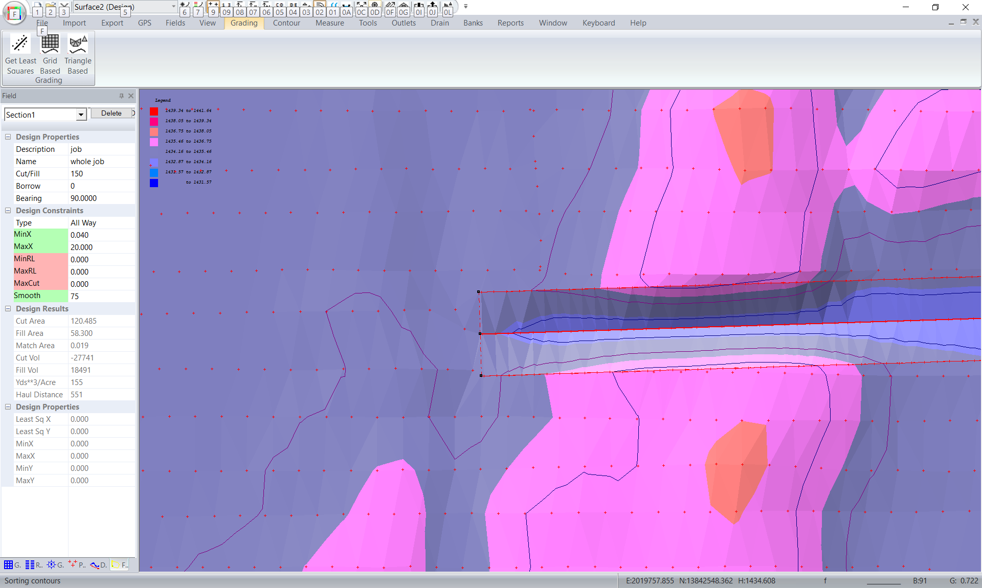
We now need to Grid the Outlet. Click on Outlet -> Grid Outlet. You can see we have points entered along the alignment as well as along the edge of the Outlet. If Box Outlet is ticked then you get additional points along the edge of the boxing.
We can now go back and repeat the Triangular Grading. We get the following. Everything looks good except at the inlet. The best fit point has led to a bit of a dip.
Move the mouse and we can see that we want the input to be 1434.378 Go back into Parameters and tell it to use an input height and set it. I also reduced the maximum grade allowed to minimise the change. Adding a smoothing distance will also give a smililar result.
Please be aware that you can have more than one outlet. Outlets can be used in the design to move water from ponding area's without necessarily crossing the edge of the triangles. In this case the water inside the area was basically trapped and we needed a lower point to force it out. In this case we may have made the Outlet shorter and still achieved an acceptable result.
|