| < Previous page | Next page > |
Drains Menu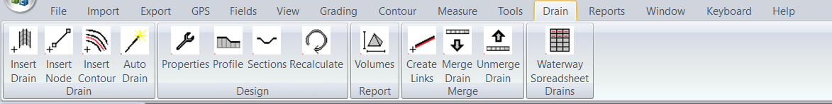
Insert Drain
Clicking on this menu item starts the process to import the drain. We draw in the drain as a series of line segments. Firstly left click on the screen. Now move the mouse and left click again at the second node. Keep going until you are happy with what you have. Click the "Enter" key to finish the process or "escape" key to abandon the complete entry. The process is the same as entering section links. Once complete the plan view of the drain is shown.
Drain Properties
Once you have inserted the drain. This drain is now the current active drain. Click on this menu item and we have the following Dialog displayed.
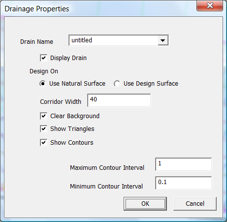
These are general parameters that define how the drain is drawn and defined.
The drain can be referenced back to the natural surface (normally 1) or the design surface (normally 2). Some instances where you would reference back to the natural surface is:
You may use the design surface for creating a drain on top of the graded surface. This elimanates issues matching up drain edges and drains.
Set the Corridor width to a value that is wide enough for the drain batters to hit the surface (daylight point).
The "Clear Background" tick box means that we can see the contours and string lines associated with the drain without background job peeping through. You can also untick this if you need to reference background as well.
We suggest that you set the maximum and minimum contour intervals to match the background surface.
Design Profile
This allows you to design the new center-line profile for your drain. Clicking on this option brings up a new view which looks like the following:
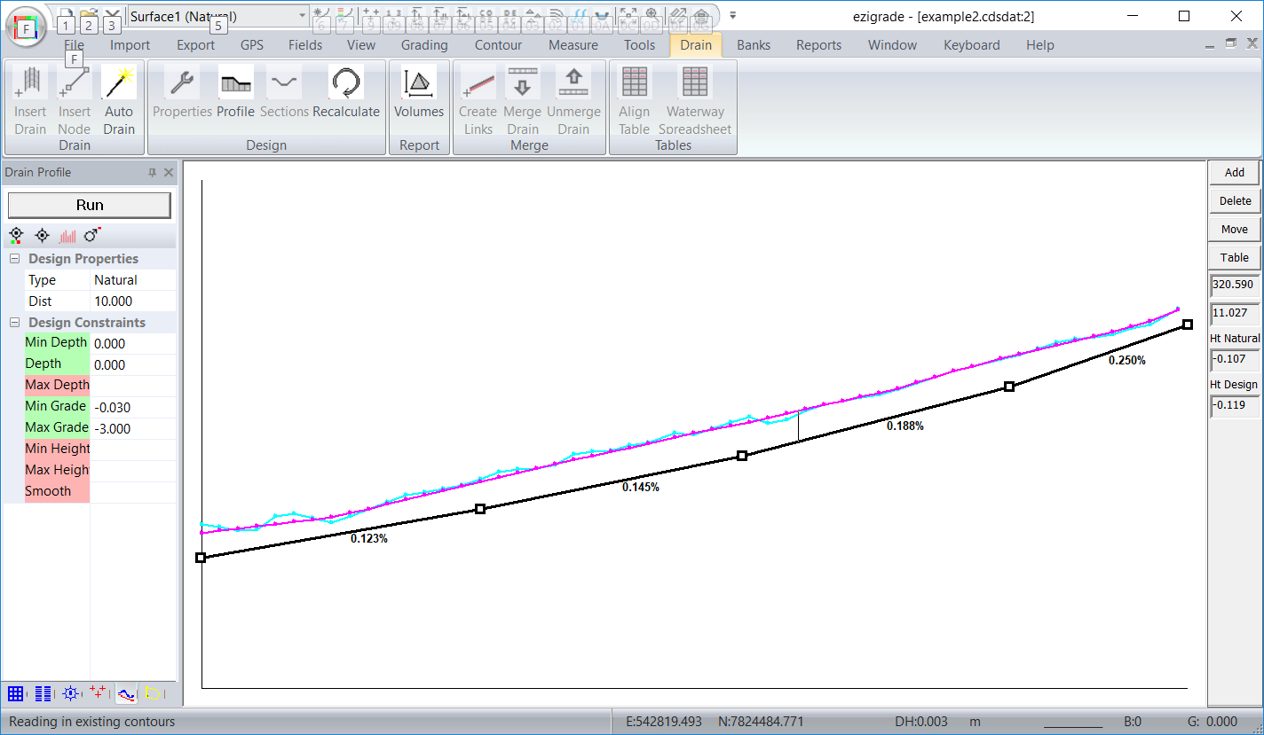
Design your profile as appropriate. At present we have the options to:
Design Section
Clicking on this option brings up a dialog that allows you to specify how the drain is drawn in a cross section view.
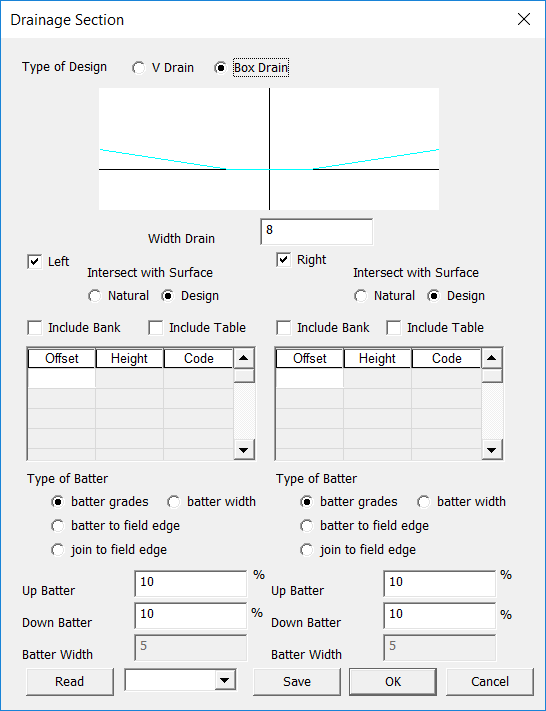
Working our way down the dialog:
Here are some typical cross-sections you can achieve:
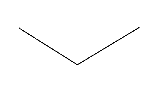
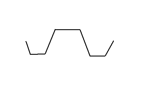
V Drain: V Drain: (Design the profile above the surface and we have a simple bank)
 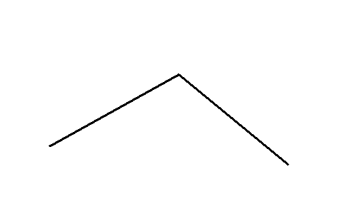
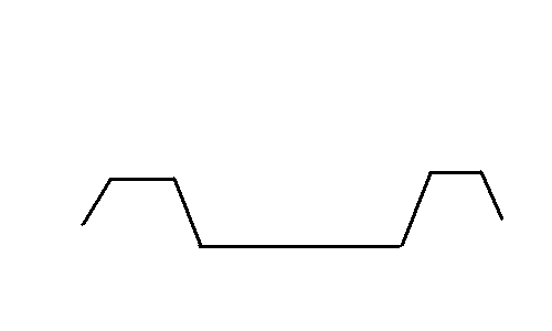
Box Drain: Box Drain: (Design the profile above the surface and we have a bank)
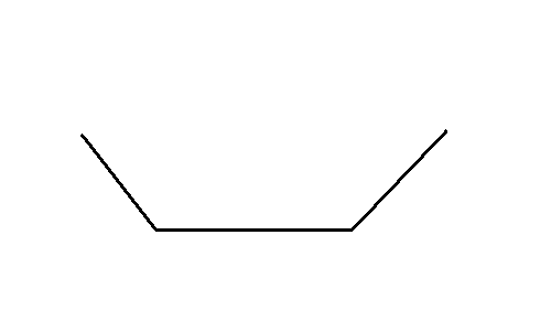 
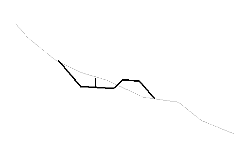
Box Drain with included banks Box drain with included banks: (Profile above the surface - with negative grade and we have a bank with 2 drains)
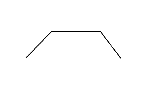
Here we have box drain and only include bank on the right:
We can use this as a contour bank
We can also use as a head ditch
Recalculate
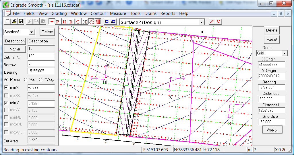
This calculates the drainage design and redraws the drain on the screen. In the example shown we have a drain that match's a grading design running both sides of the drain.
Merge Drain into Natural
This takes the visual design we can see on the screen and creates a modified natural surface that reflects this design. Once done the drain is now locked. This enables us to seamlessly unmerge the drain later if required. To see the modified surface untick the drain icon at the top of the page.
For advanced users: The software adds in extra points to the database and creates appropriate breaklines that reflect the strings shown upon the drain. Also any existing points within the drain corridor are set to non-contourable. You can go into CDS and tweak these values if necessary. However it shouldn't be necessary.
UnMerge Drain
Reverses the process above and sets it back to original.
Merge Drain into Design
Same as above except we are using the design surface. If we merge the design above we get:
Unmerge Drain Design
Resets the above process.
|