| < Previous page | Next page > |
Export Trimble Field Level 11
Use this option to create a Trimble compatible (.gps) file. This is compatible with Trimble FMX and TMS controllers.
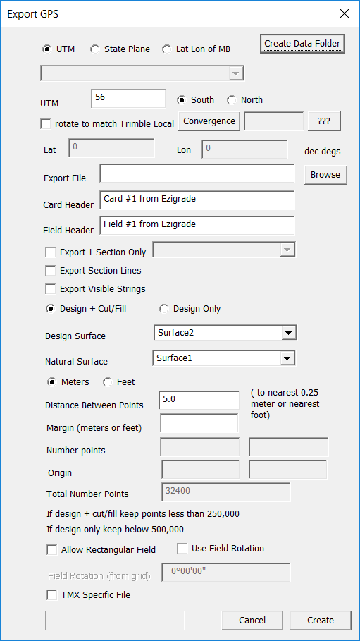
Clicking on this option brings up the following dialog:
If you look at the dialog - top right you will see an option to "Create Data Folder".
The Field Level2 system expects the data to lie with certain folders on the memory stick that you insert into the system. This will create a blank compatible file system for you. Plug in a blank USB stick to your system and run this option. It will create the following File structure:
AgGPS
AB Lines
AgGPS
Autopilot
Data Dictionary
Designs
Diagnostics
Multiplane Designs
Prescriptions
Productivity
Summary
VRC
The Trimble system expects the designs to live in the "Multiplane designs" folder. It will not find the file if it is put anywhere else.
Coordinate System (UTM)
At present the conversion expects the data in either UTM, State Plane or any other system as long as we know the lat/lon of the Master Bench Point. The system expects the designs to live in the "Multiplane designs" folder.
If the "UTM" radio button is ticked then you need to select either the northern or southern hemisphere. You also need to enter the UTM zone. In Eastern Australia you are looking at 55 or 56; while mainland United States lies between 12 and 18.
If we are using UTM data; you need to know how the data was obtained. If you have imported the data from a "multiplane.txt" file then the Master Bench point is imported in UTM coordinates, in either feet, survey feet or meters. The multiplane.txt file lists all the other points as an easting/northing value from the Master Bench points. Ezigrade gives these points a coordinate based on the Master Bench point. ie we really have a local coordinate system where the master bench has UTM coordinates. If your data was obtained this way then the .gps file created will match what the Trimble system expects. As a rule of thumb if you survey and grade using the same GPS system then everything should work out.
If you obtained your UTM data from a different system then it is almost certain that the data will have a swing compared to a local coordinate system at this point. This is because UTM is based on a flattened sphere while Trimble expects data based on a plane. The UTM data grid north will almost certainly be different to true north of Trimble. If you are on the Central Meridian of the zone or at the equator then they will match. There is a routine in Ezigrade which allows you to fix the data to a local system. Look under "Tools - UTM to Local". If you run this we suggest that you first do a "File - Save As" and store your data in a new file. Then run the conversion on this file. This leaves original data intact.
UTM rotate to match Trimble
If you have data picked up in UTM coordinates. ie every point picked up is on the geoid. Then ticking this box will correct the data when the Field Level2 file is created. If you have picked up data using FL2 then do not tick this option.
Coordinate System (State Plane)
If you have data in State Plane coordinates then we can use this as well. As the State Plane system uses smaller zones, the convergence is typically less. You need to use your professional judgment on whether it is important. The convergence can be calculated and there is a routine in CDS to rotate the data if it is important. Also you can use your FL2 system to compare the bearing between two points in the field and compare it to the same two points in your job. This will give you the rotation error and you can rotate your data as necessary within CDS. Click on the link to Field Rotation Errors below.
If you have data in a local coordinate system then we can use this as long as we know the latitude and longitude of the master bench point. Again there may be a rotation error. Again if we know the convergence or can measure two points in the field using FL2 system then we can get a result to good tolerance's.
If you need more information on Rotation Errors then please click to view the link. Field Rotation Error's
Export File:
Click on the Browse button and browse to the appropriate directory. If you writing directly to FL2 compatible USB stick then make sure the file goes into the "Multiplane Designs" folder.
Card and Field Header:
These fields can be filled in if necessary. They may be handy for the operator but in practice most users don't bother changing the defaults.
Export 1 Section Only
This is handy if you have a large job. This allows you to split up the job into smaller .gps files and increase the density of the data in the export file.
Strings and Section Edges.
It is normally worth exporting strings. They are a handy guide for the operator. Please note that Trimble doesn't know about arcs and circles; only straight segments. If you have strings that contain arcs then there is an option within CDS that will split the arc into straight chords.
Distance Between Points etc
The FL2 file has the data setup in a grid pattern. There is gridded data which contains the "designed height" and another optional grid that contains the "cut/fill". We normally suggest that you export the cut and fill as well as it is a good reference for the operator.
As mentioned on the dialog. We can export gridded data in 0.25 meter increments if using metric or alternatively in 1 foot intervals. The tighter the grid we specify; then the more points that are used. The FL2 file is a fixed size so there is an upper limit. We normally suggest 250000 points if including cut and fill and upto 500000 if only doing a Design. Please note that some FL2 systems fall over if the data is too close together. As a guide I believe MultiPlane will not put out points closer than 8 feet.
The new TMS monitor allows larger data files. At present we have not yet implemented compatible files; it is on the list.
The margin specified puts some null grid points further out around the edge. Operators ask for this feature so it must be useful. Make the margin a multiple of the grid size. However Ezigrade will correct things if it is not.
When the grid is created Ezigrade puts the tightest square around the data that it can.
If you tick the "create rectangle" then the tightest rectangle around the data is created.
If you tick the use "Field Rotation". Then either the tightest square or rectangle is created at the appropriate rotation. The rotation is set from the "grid". Click on the following link for more information.
|