| < Previous page | Next page > |
Contour Menu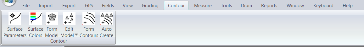
These functions help you create a digital representation of the job surface (triangles or digital terrain model). From this you can create contours, color maps of heights and slopes. The grading routines also work on this data.
The contour options in Ezigrade are a subset of all the options that are available in CDS. Ezigrade includes those options that are more specific to the grading process. You have the option of creating the job initially in CDS and opening it up in Ezigrade later.
Surface Parameters
The surface parameters allows you to define the functionality of the surface. Which points are used in the surface etc. There are three tabs across the top which allows you to set parameters for "Surface Parameters", "Surface Point Selection" or "Surface Colors".
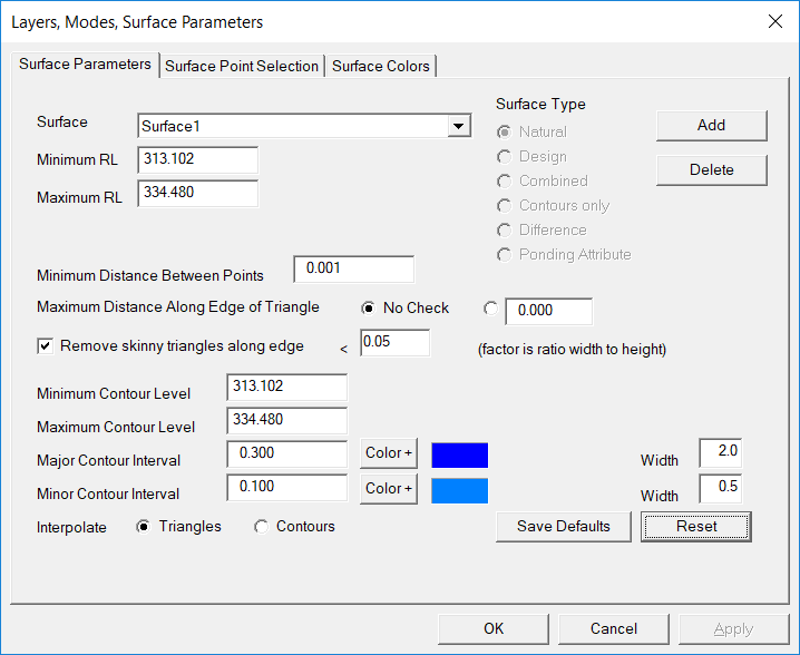 Surface
This defines what the surface represents. The following types are currently defined:
Clicking the "Add" button allows you to create a new surface. The "Delete" button will remove the current surface.
Minimum and Maximum RL's, Contour Level.
Use these fields to restrict the points used in the terrain model, and restrict the heights to display contours. We suggest you set these values with the "reset" button which sets them to the job extents. Please note that if you add in new points to the job these values don't change automatically. You either need to manually change the values or hit the reset button.
Minimum Distance between points
Normally this is left at 0.001 However you can exclude points that are too close together.
Maximum Distance along edge of triangle
This means that no triangles are formed which would contain a side whose length is greater than this value. Setting this value can control the long skinny triangles that often form around the edge of the job.
Remove skinny triangles along edge
If selected Ezigrade looks at the triangles along the edge of the job and if it finds long skinny one's with the ratio of shortest edge divided by longest edge is less than the value entered then they are removed.
Major and minor contour intervals
A contour is a line that joins points of the same height. Change these values to increase or decrease the contour density. Make sure the major interval is a factor of the minor interval. You can also set the colors of the major and minor contour lines. If you have a difference surface then you can also set the negative major and minor contour color.
We can also set the line width if the contours. For example we may have a width of 2 for major and 1 for minor. You can also enter a value less than 1. In this case a dotted/dashed line is drawn as follows:
Save Defaults
When creating new surfaces or creating a new job; we often want to keep our favourite setups. This button saves the contour interval, contour colors and contour widths. Once saved these values are automatically retrieved when we set up the next new job.
Surface Point Selection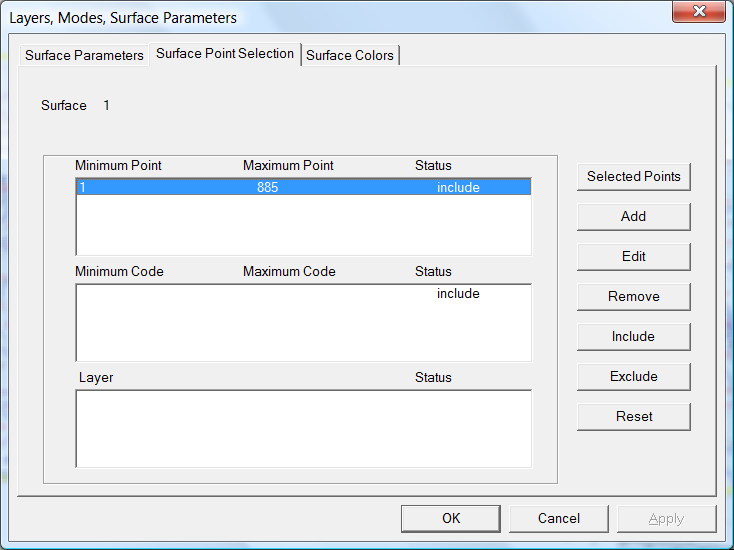
This allows you to define and refine which points are used in the surface creation. Normally for graded jobs you would use all the points in the job. Pressing the "reset" button will fill in all the values with the job extents. Alternatively you can simply delete all the entries and all the points in the job will be used.
Please note that if you add in extra points to the job, you will need to expand the range of points, codes and layers used. We suggest the reset button.
Surface Colors
This allows you to color in the triangles displayed upon the screen. This is often a good way of visualizing how the height varies across the job. This often gives a better feel for the job compared to a 3D view.
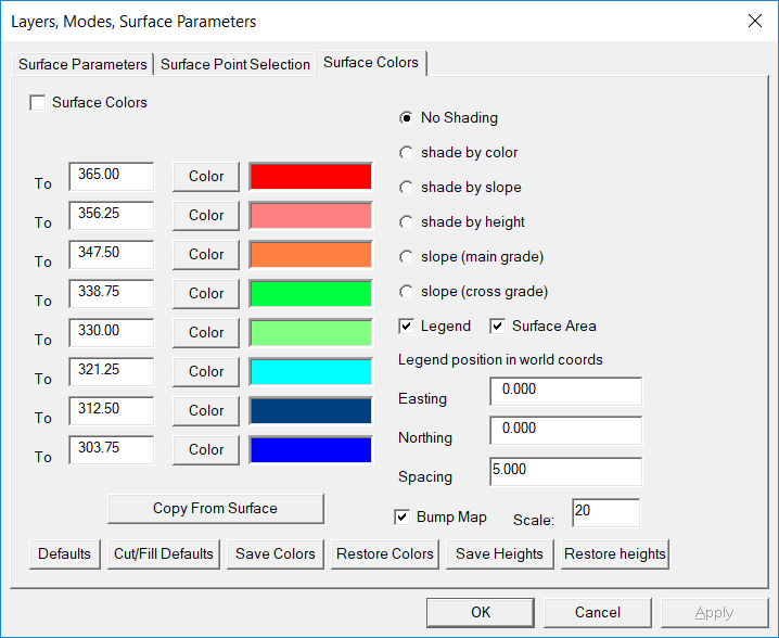
Fill in the values to the left and set a color to represent the height values. Please note that the lowest height starts at the lower left and works up the screen. We suggest that once you picked a color palette that you like then you save it away using the "save colors" button. You can then restore it in future jobs.
We also suggest that you make a habit of defining the surfaces in a consistent order. For example surface1 is natural, surface 2 is design, surface 3 difference etc. This way save / restore colors makes sense.
The "Copy From Surface" button will copy the values from one surface to another. Often you setup surface 1 at predefined intervals and colors. After grading when a new surface is formed these height values are calculated automatically by Ezigrade. Once we look at surface 2 colors; by clicking the button we can copy these predefined values directly from surface1 into surface2. This makes it easier to compare actual heights around the job.
The "Bump Map" is a tool used by Cartographers to give the illusion of a 3D surface. Slopes facing the sun are colored in a lighter shade while surfaces sloping away from the sun are shaded a darker color. You can turn this feature on or off and also specify a value.
Form Model
Clicking the button, forms the model. Reform the digital terrain model every time heights on points are formed or new points are added into the job.
Surface Area
Ezigrade uses the extents of the job and this option is currently inactive. If you need to define regions of the job that you only wanted triangles formed then you have the option of closing the job in Ezigrade. Open job up in CDS and form the restricted triangles there.
Edit Model
This contains the following sub-sections:
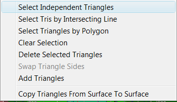
You would normally only need to use these routines in grading jobs to remove any long skinny triangles that you often get around the edge of the job. You can select triangles individually, by intersecting line or by a bounded polygon. Once triangles are selected hit the delete key to remove them. You also have the option of manually entering new triangles here as well.
Copy Triangles from Surface to Surface
This is a handy utility to remember. Once you have created a surface using for example natural surface heights, you can simply copy the triangles to your design surface and your difference surface.
Create Contours
Clicking this button creates or recreates the contours on the job. Redo this everytime you change either the underlying digital terrain model or if you change any heights upon points.
|