| < Previous page | Next page > |
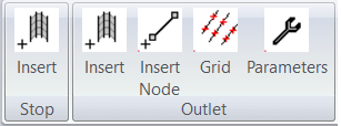
Outlet Menu
This allows you to create either a stop bank or an outlet. A Stop bank is used in conjunction with AllWay grading. It is drawn around sections of the edge of the job and tells Ezigrade that water can't escape through the "Stop Bank".
An outlet is similar to a drain. It has been designed to simplify the process of controlling water-flow. Particularly when used with AllWay grading. You can sketch in a centre-line and set a nominal width. You then fill in some parameters such as minimum and maximum grade and the software designs the structure for you. The AllWay grading knows to use this when calculating the triangle based grading. Please see tutorial later in the manual.
For more user control you can use a drain to achieve the same.
 Insert Stop
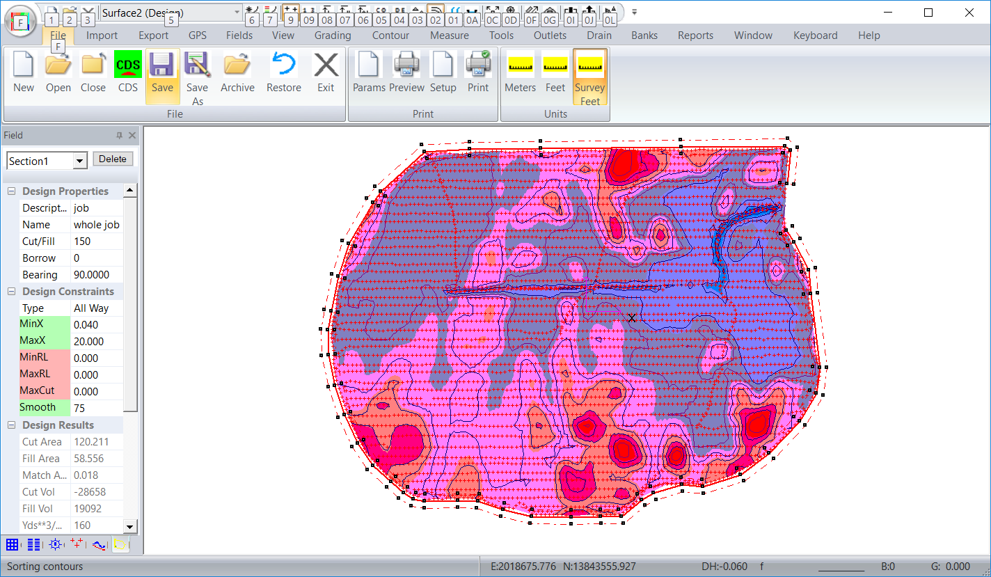
Clicking on this menu item starts the process to draw the "Stop Bank". We draw in the drain as a series of line segments. Firstly left click on the screen. Now move the mouse and left click again at the second node. Keep going until you are happy with what you have. Click the "Enter" key to finish the process or "escape" key to abandon the complete entry. The process is the same as entering section links. You will be asked for a nominal width. It is important that the "Stop Bank" includes all the appropriate points on the edge of the job.Once complete the plan view of the "Stop Bank" is shown.
In the screen shot below we have drawn a "Stop Bank" around the job. In this case we want to ensure that water only flows out of the area in the north east corner of the job.
 Insert (Outlet)
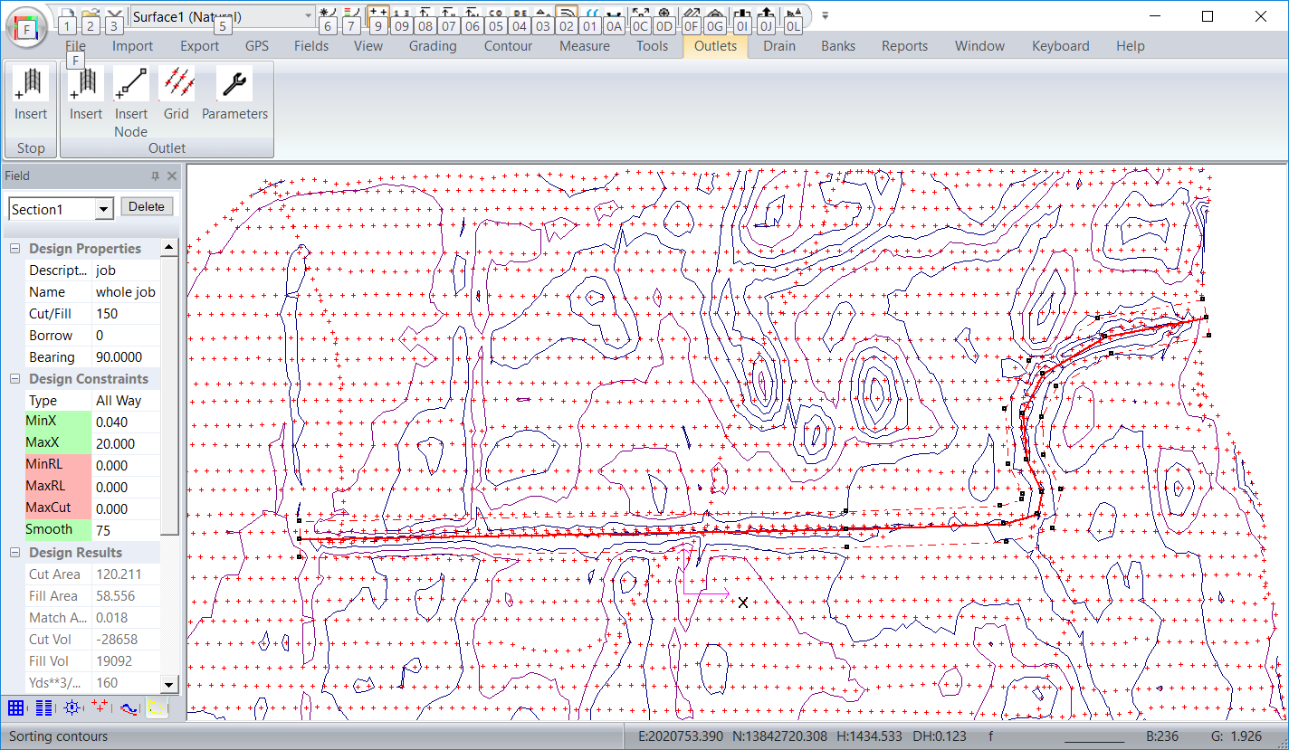
Clicking on this menu item starts the process to draw the "Outlet". We draw in the outlet as a series of line segments. Firstly left click on the screen. Now move the mouse and left click again at the second node. Keep going until you are happy with what you have. Click the "Enter" key to finish the process or "escape" key to abandon the complete entry. The process is the same as entering section links. You will be asked for a nominal width.
The outlet can enter and exit the job or just drain a ponding area in the job. In the screen shot below we have an example where we are pushing water out of the north east corner of the job via an outlet.
In the screen shot below we have The It is important that the "Stop Bank" includes all the appropriate points on the edge of the job.Once complete the plan view of the "Stop Bank" is shown.
Insert Node
To insert a node select this menu item and then left click on the screen where we want the additional node. If you have more than one outlet in the job; then it is important that the outlet is the active one. You can do this by left clicking on the outlet alignment first. It will be drawn in green. To delete a node left click on the node to select and then hit the delete key.
Grid
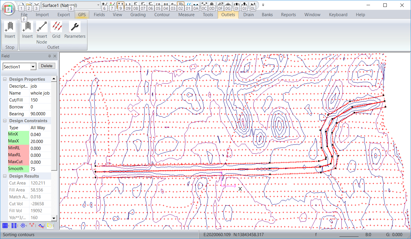
This puts a new set of points inside the outlet. These points are spaced so that our best fit algorithms can work efficiently. The existing points within the outlet area are removed from the database. They are stored internally so that we can re-instate them if we decide to move or remove the outlet. The screen shot below shows the outlet with gridded points. You can see that we have added in points along the centre-line and also along the outlet edges. We have also added in breaklines aling the center and the respective edges. This makes sure that the triangles form correctly. Compare it with the screen shot above.
 Parameters
This brings up a dialog where we can control the parameters of the outlet:
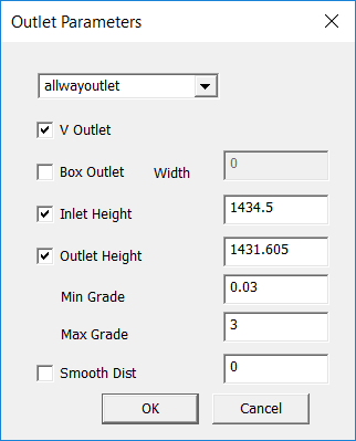
If there is more than one outlet then you can change the outlet being editted in the combo box at top of the dialog. We have the following parameters:
|