| < Previous page | Next page > |
Vegetable Farm Design
This tutorial shows you how you would approach the design of a vegetable farm. The vegetable farm consists of a number of individual sections with vehicle access / roads / drains aroud each individual section. We have been presented with the following raw data.
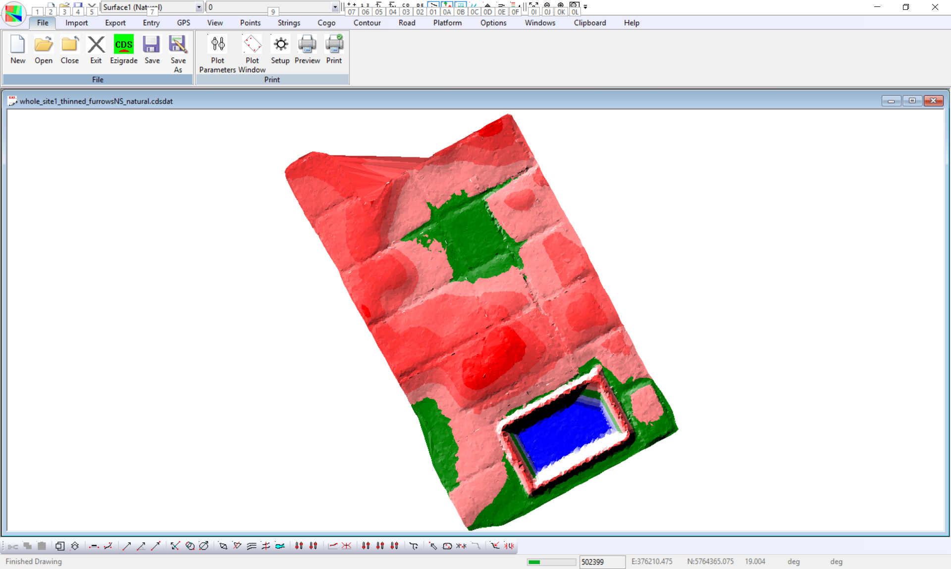
To create the following we imported the data into CDS. We created trianges using the contour -> form model menu item. We turned on the color display using the contour -> color dialog and set a range of colors. When we look at the model we can see the individual sections. Between these isolated sections we have vehicular access.
Our design brief is to create a design where water flows either North or South within each section. Water can't flow off to the East or West as the farmer plants the vegetables in furrows.
For our first step we need to create sections around each paddock. From what we have you could guess some section links and click them in. However out client has drawn the section outlines with acad. This is an important point. Just because we are using Ezigrade or CDS. If you can create some data in another package that you are proficient in then use that other package. As long as we can get the data back into CDS/Ezigrade. In this case we can import DWg data within CDS.
Importing the track lines from Acad
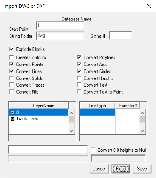
When importing a DWG it is important that we only import exactly what we need. I suggest that in Acad you create a new DWG and copy and paste only what you need into this new file. After doing this click on Import -> DWG. Now click Read. The layer names etc are filled in. At this time you can turn on/off layers etc. Now click on the Save button.
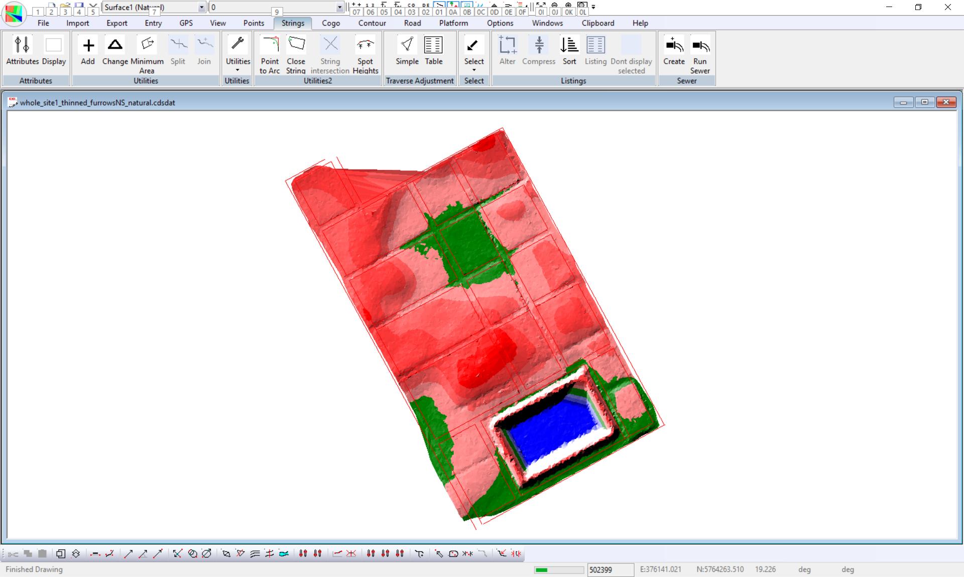
The tracks are imported into the job If you don't initially see the lines then click on Strings -> Attributes and make sure that we have some strings and that they are clicked on so we can see them. We have as seen below:
Now open the job in Ezigrade. We wish to enter the section outlines now. Click on Fields -> Field Edge. You left click the start point, move the mouse - left click again. Work your way around the section so that it closes. Hit the Enter key or Escape key to exit. If you are not sure of this procedure then please look at some of the earlier tutorials where this is explained in greater detail.
Repeat for all the sections and we have something such as this:
Our design brief was to have at least 1% drainage either north or south. Before thinking too much I have set every section to use All Way grading with a minimum grade of 1%. Haven't worried about smoothing yet. After running the grading -> tri based I get this result.
It is obvious that the edges of all the sections are very jagged. When doing the tri based grading Ezigrade only calculates a design height on points within or on the section. Yes we could do this automatically; but if things go wrong it is hard to correct errors without some form of user control. To fix this Ezigrade has an option to place points along a section. This will allow the design to go right to the edge. You need to select the appropriate links. In this case you would select all the links on outside of sections. All links should be green such as this:
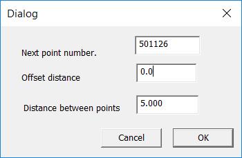
Click on Fields -> Add (points on links).
A dialog pops up and enter an offset of 0.0 to force points on the section link. I used 5m but this is up to the user.
After running this Ezigrade reforms the triangles so that these points are included in the model. We suggest that you are reasonably sure of section placement before doing this. If you move a section link then the extra points are automatically deleted.
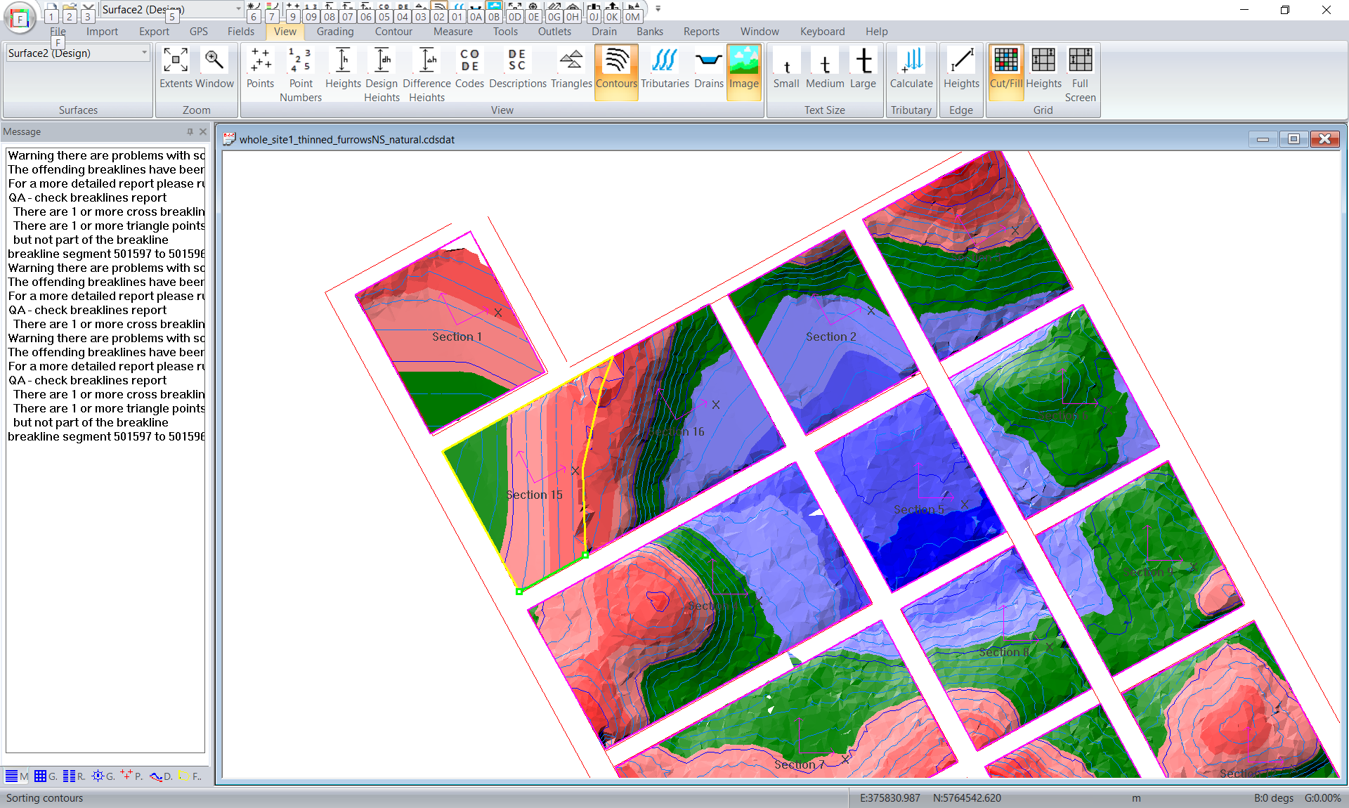
If we run again we get this:
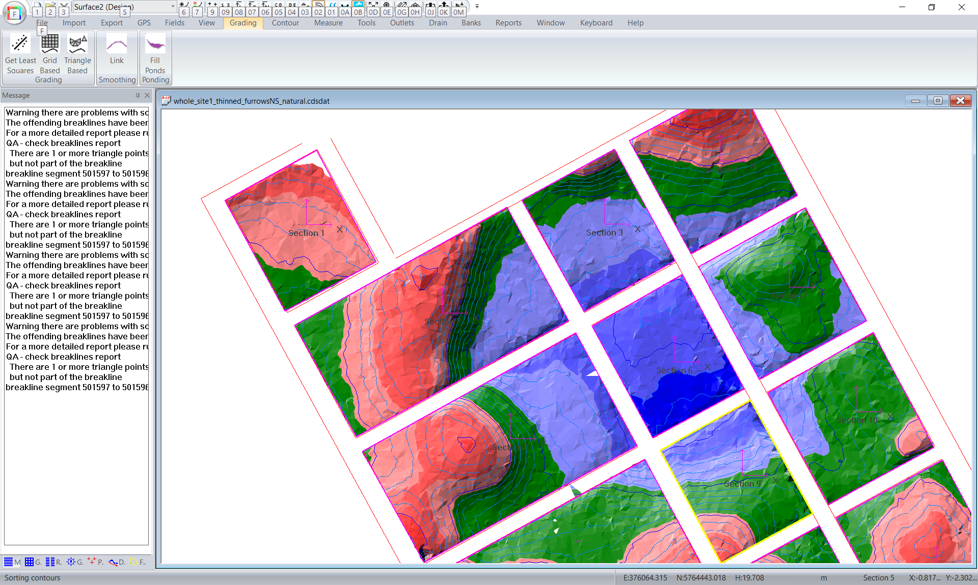
You may notice that on the left of the screen that we have some warnings. These are some issues with the breaklines. When we added the perimeter points Ezigrade also entered some breaklines to force triangles to form along the section edges. If there is an issue then you will find the issues showing up in the DTM and the contours. If the contours are OK then the job will be OK.
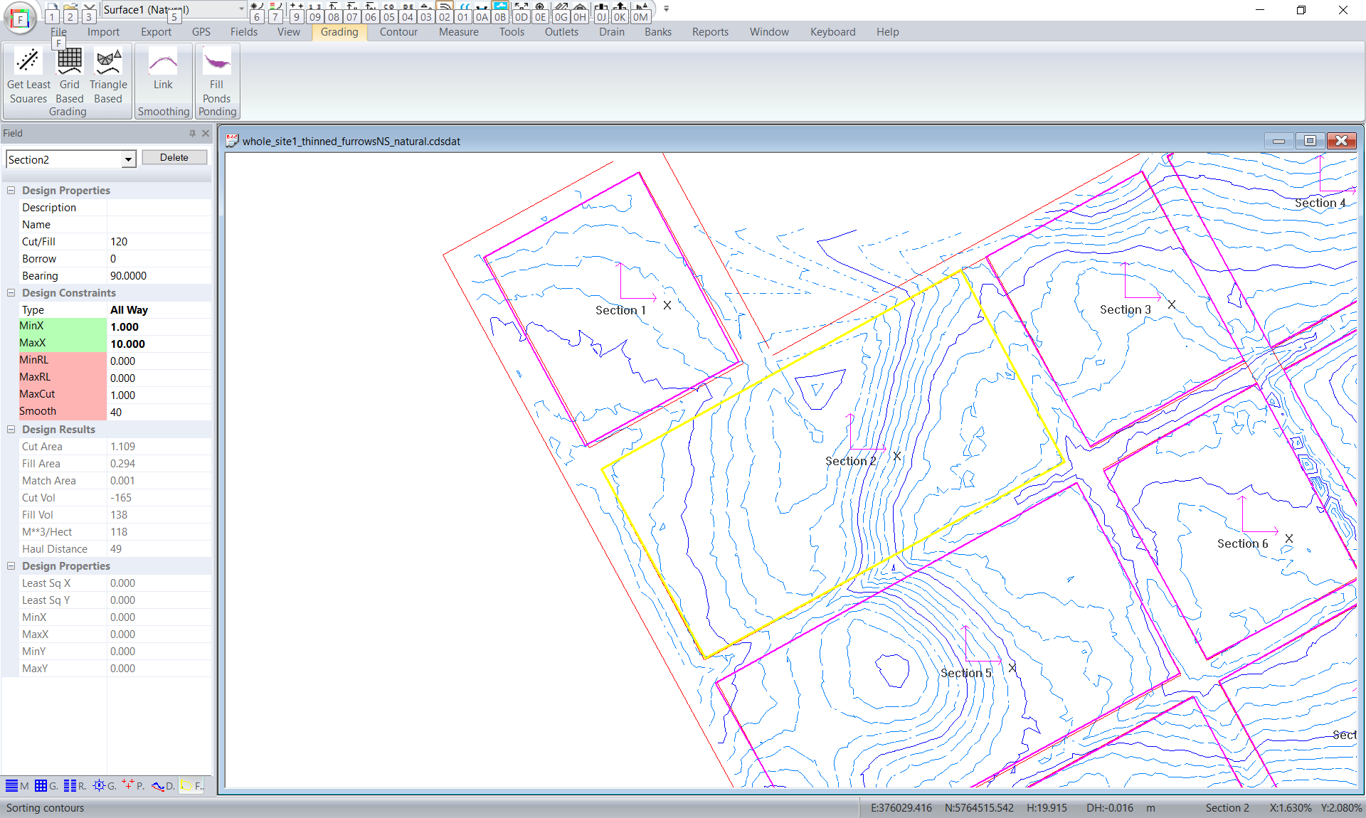
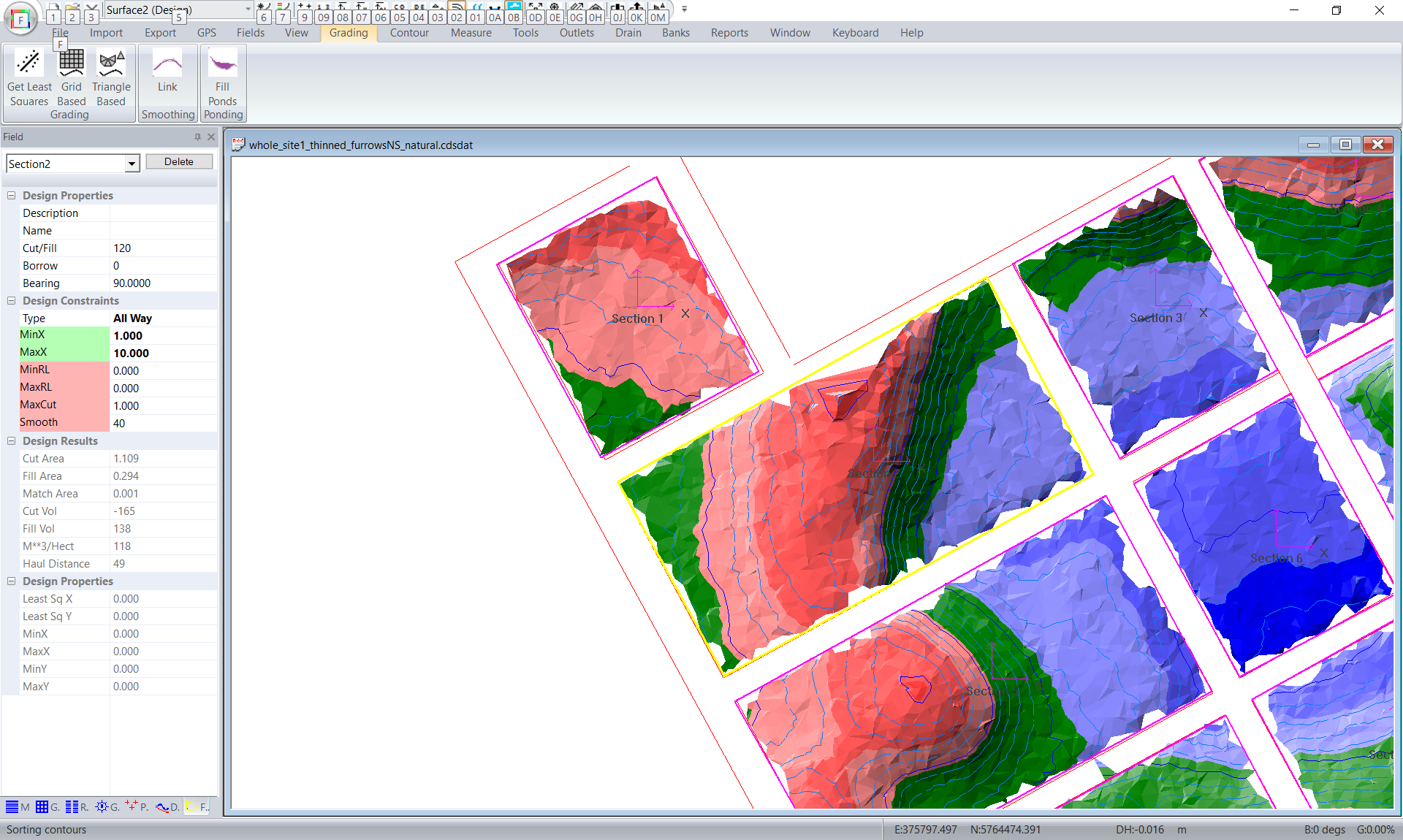
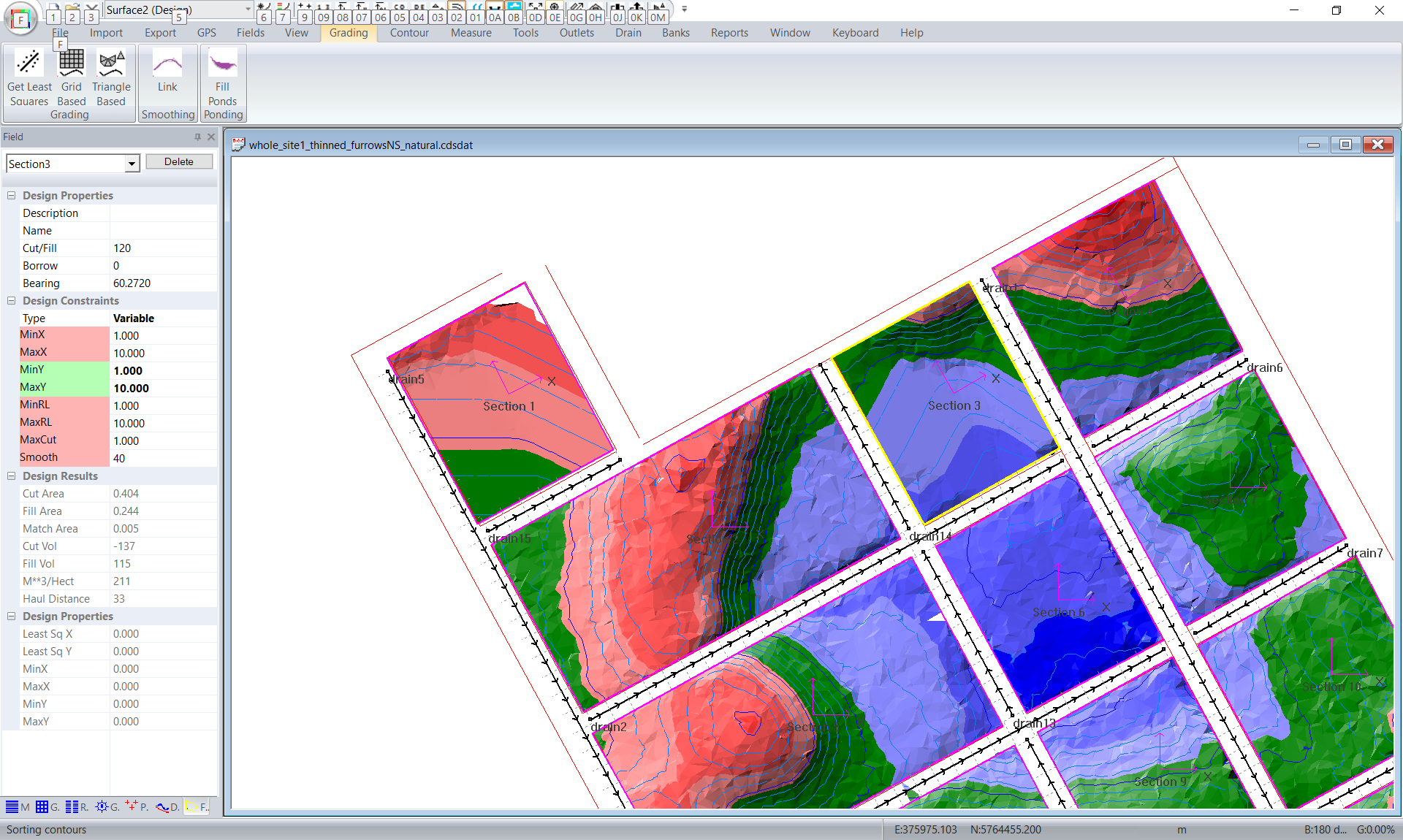
Now I would look at each section in turn and work out whether the water is going to drain in North or South direction remembering that we have furrows on each section. To check the grades in water flow we need to select each section axes and rotate it so it is running parallel to the section. You can clck on the axes. You will see the red grip point. Click on this and rotate. You can also enter the value exactly in the bearing box in the Field Design docking window at the left of the screen. In this case it is not too critical so I have simply rotated the axes by eye.
If you look at Sections 1,3 and 4 (and others) you can see that the water will only be flowing one way across this field. So for section 1 we are going to change the field design parameters. Change to Variable design and set the Y value to be between 1 and 10%. Y axis is pointing uphill. We can see that 1,3 and 4 are looking OK.
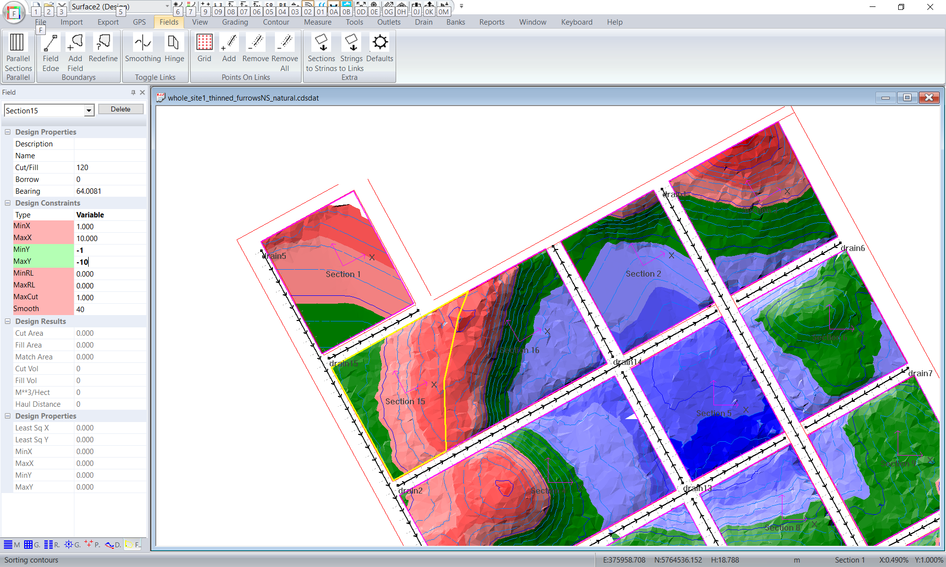
If we look at section 2 we can see the design is not quite there. The water does either flow North or South but there are some areas that are less than 1%. The solution is to subdivide section 2 into 2 parts and force water north in half and south in other half.
Click on Fields -> Field Edge and I would click in some links along the ridge. Ezigrade will split the section and create two new ones. We have replaced section2 with section15 and section16. For section15 we have set as variable grade and have set the Y grades as -1 to -10. Again we dont care about in X direction as we have furrows. In section 16 the Y grades are 1 and 10%.
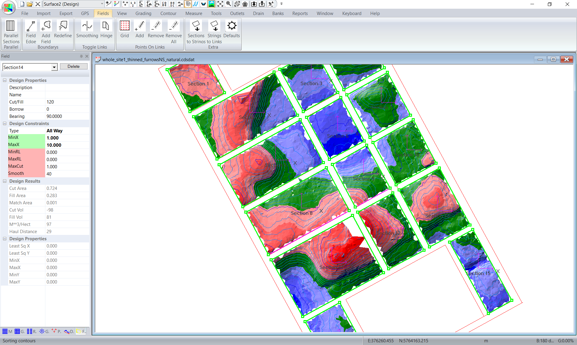
We have now fixed sections 1,2,3 and 4. You now need to go through and modify each section in turn as appropriate.
Once we have modified all the sections as appropriate we can regrade. It is also now worth putting on smoothing. With the smoothing we don't want the neighbouring sections to modify our section. To do this click on all the outside sections and click on Fields -> Smoothing. If they are red soothing does not occur across the section. We don't set the internal section lines as we want to smooth across them.
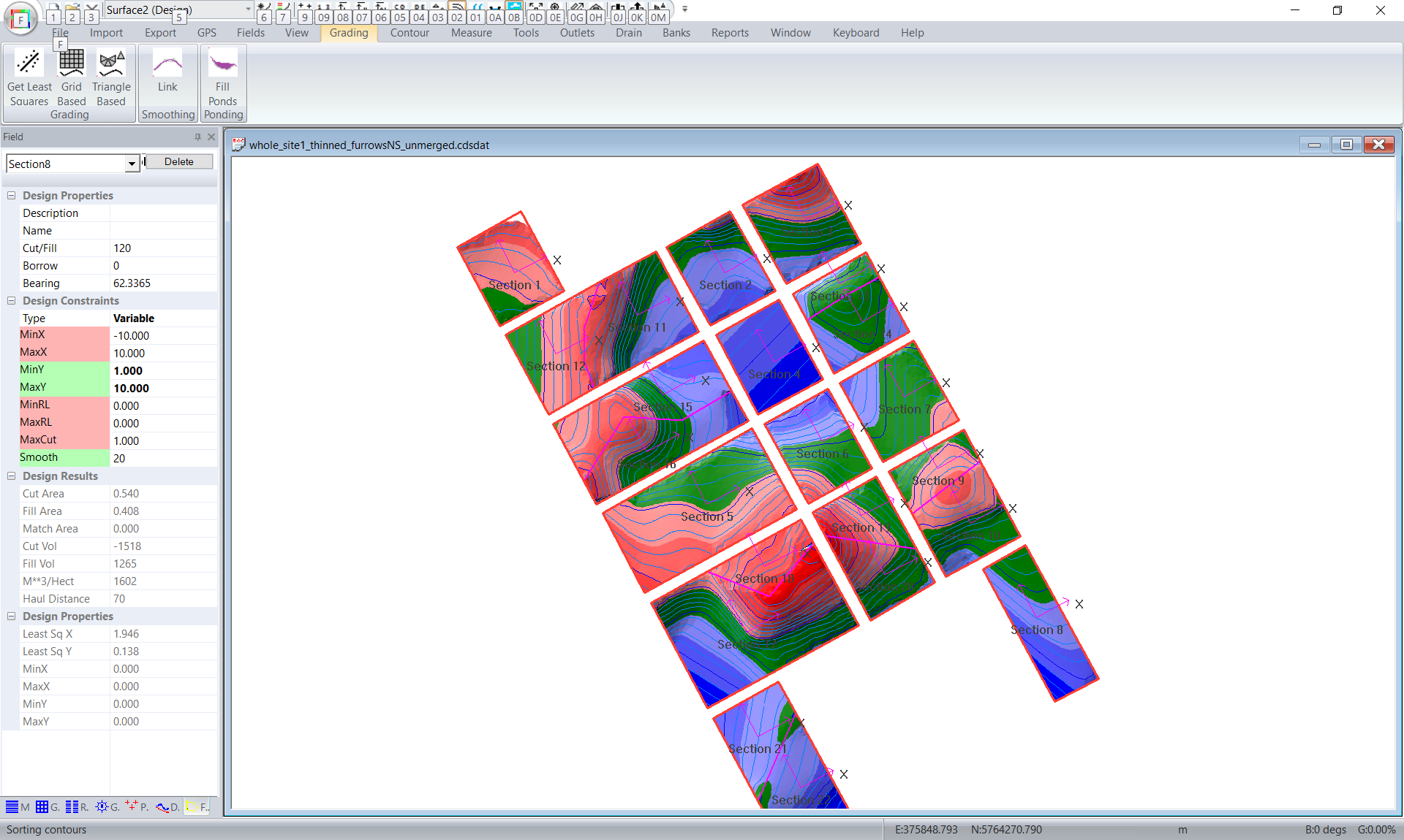
The sections have now been designed.
Designing the road / tracks on the outside of the sections
Our client also wants the tracks on the outside of the sections to drain as well. Ezigrade as the drain routines that we can use. You should note at this stage that Ezigrade is quite capable of designing a drain / bank etc which can be used as a road. However it is not optimised in helping to tie in the roads to each other. If you have a civil engineering software such as Civil 3D you can certainly import the model as is to a different software and do the design there.
I will show you how you can design this in Ezigrade. I would start at the main road which is the North - South drain a third back from the right.
To click in a Drain you click on Drain -> Insert Drain. I have set up a drain topology as seen below. This is not necessarily the best way. You need to look at where the water flows of the sections and how to best lead the extra water away as well as making a road surface. I have main north-south drain towards the right and another full length drain on the left. I then put in some cross drains.
I have finished with some short north - south drains joining these cross drains.
This is all very much up to the user. Also the north - south drain to the right has a pump which pumps water from it into the dam at the bottom.
Now left click on "drain1" and click on Drain -> Profile
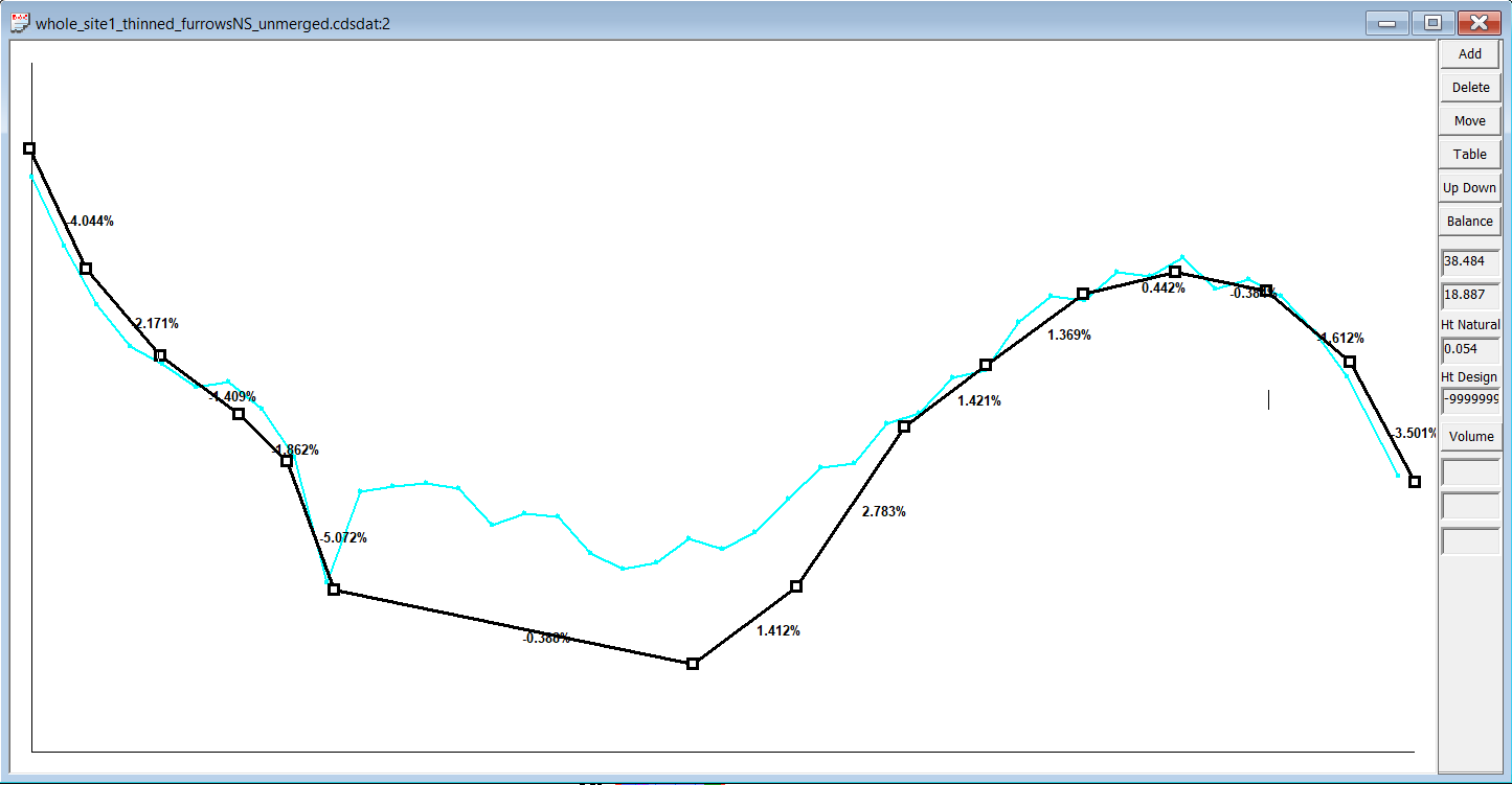
Also the flat spot in the middle needs to be slightly lower than the water running of section4.
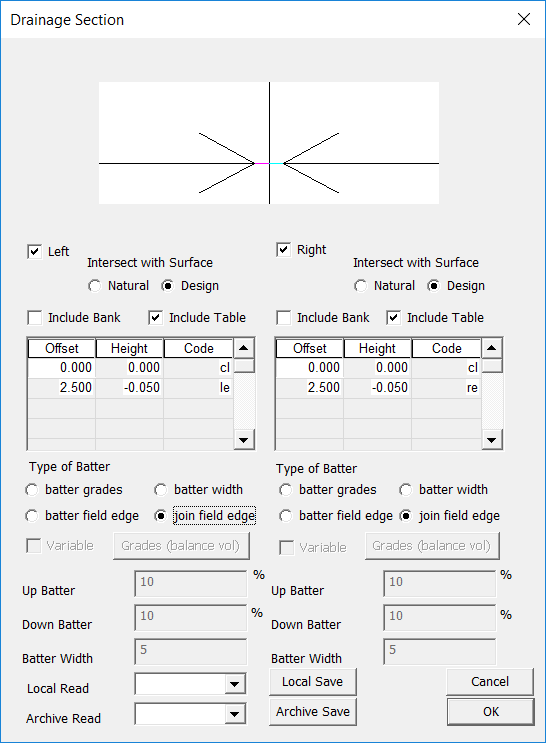
We now need to design the cross section of this drain. Close down the profile (click X top right of the view) and click on Drain -> Sections. Our client wants a typical road crown with a 2% cross fall. Fill in the "include table" to create this section. For the batter we want to join to the existing field edge. So we fill in as below. As we are using the same section for all our drains then you can save the section as a name and import it into our other sections.
Now click on Drain -> recalculate to see what it looks like.
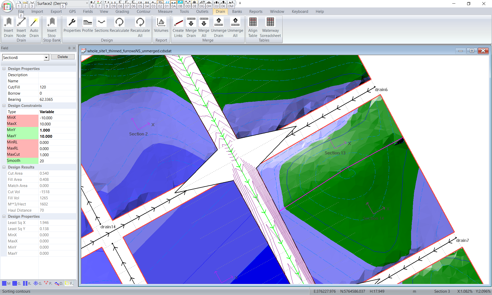
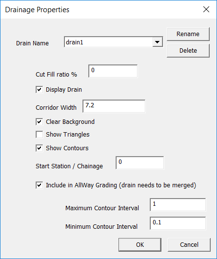
It looks OK except where we don't have a field at the edge to join into. To fix this click on Drain -> Properties and change the corridor width to something just wide enough. I have used 7.
We now have which is much better.:

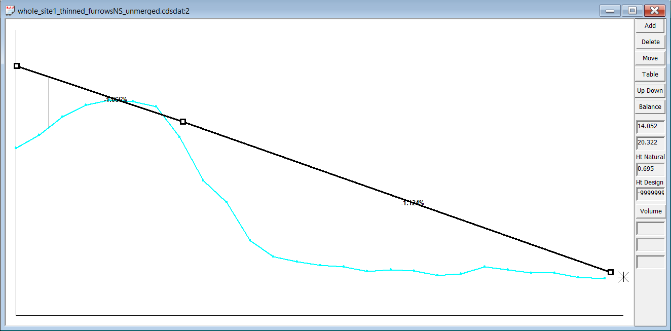
We now want to design one of the cross - drains: You notice there is a star at the right. This is the height of the existing drain. We have also been asked to keep the drain slope to be greater than 1%. Unfortunatel this means that we have drifted from the natural surface which can lead to issues.
In this case you could go back into the first drain and sink it where this drain exits. Unfortunately this also means we have more cut in the main drain / road. So this process is really up to the individual designer. Maybe you go back and run water down drain13.
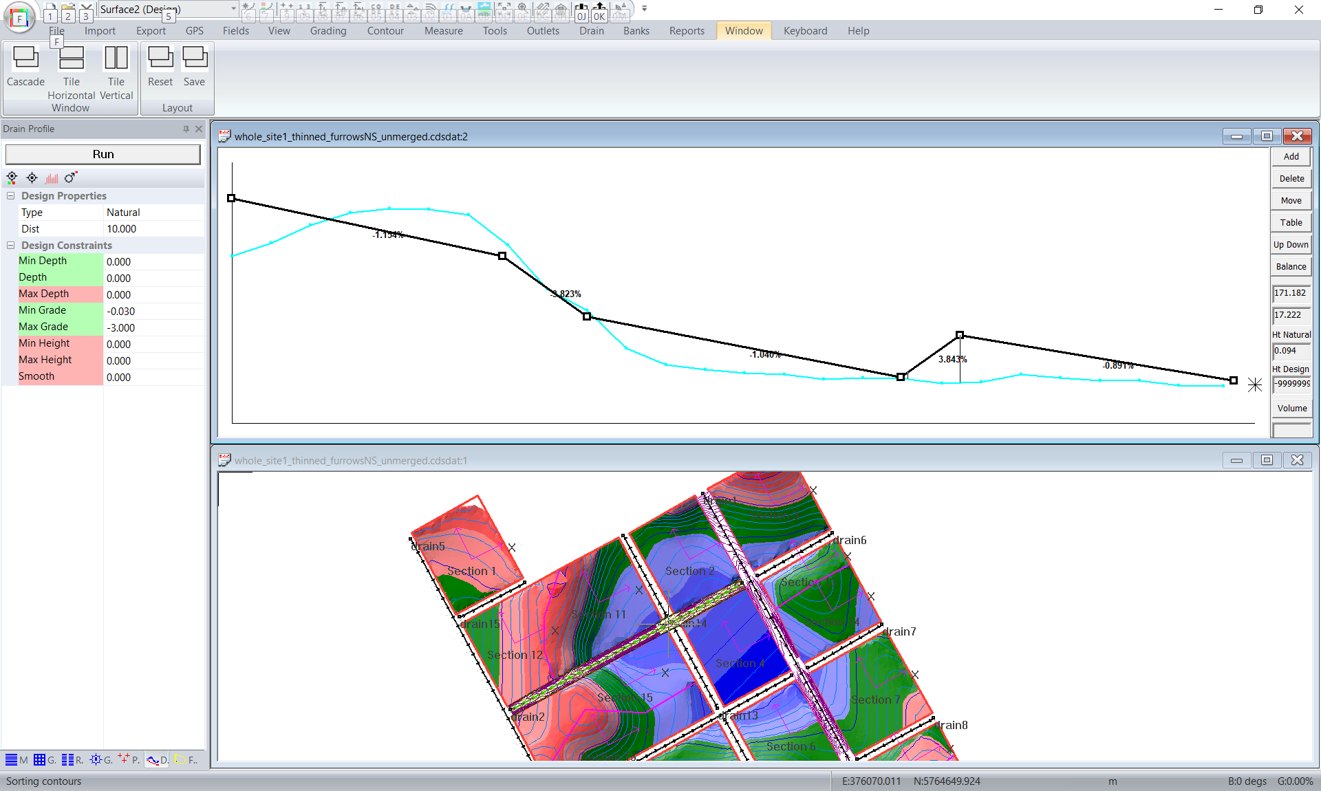
After you click on Drain -> Profile click on Window -> Horizontal. When you move your cursor along the profile you get a cross in the plan view. This way you can identify the low point and design appropriately.
So you work your way around the drains trying to match your design constraints. To this end I would suggest that you don't merge your drains until you are happy with the result. For example after trying to match one of the less important drains it means that you may need to bo back up to the parent or gradparent drain and work through again.
You will also notice that the road / drains are designed so that they dont intersect. If you get all the heights in the drain right then the design should be very close at these intersections. For completeness you probably should decide each individual intersection. Does the road crown go through the intersection and the side road stop. We also could have drains along the edges and these need to be designed appropriately. You can do kerb returns in CDS but it is probably overkill. A good grader operator can probably do this by eye.
Once you are ready to create the final design. I would save the job and click on File -> Save As and create a new job which is the merged job. This makes it quicker to go back rather than unmerging everything etc.
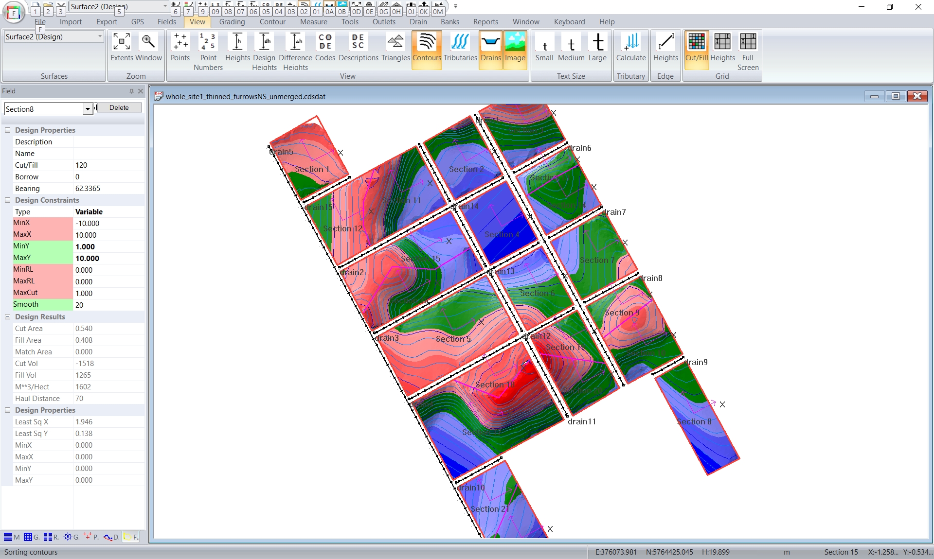
Once you are happy click on Drain -> Merge All and you should get something like this:
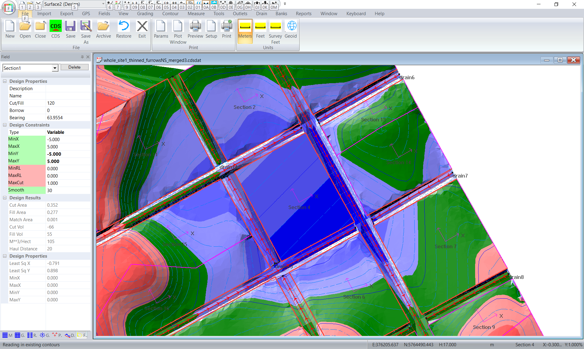
Check the intersections. Look for lots of contours around an intersection etc or areas with lots of intersections to a field edge. We may be able to improve on this.
Hopefully this tutorial will show you the general design procedure for more complicated examples.
|