| < Previous page | Next page > |
Pipe Design
In this example we are going to design a reasonably straight forward Pipe network. This example is in metric. However if you have your job in either international or US survey feet then you get to use imperial measures like inch's.
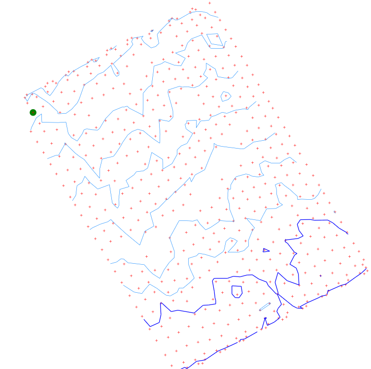
We have taken a survey and we have the following points picked up.
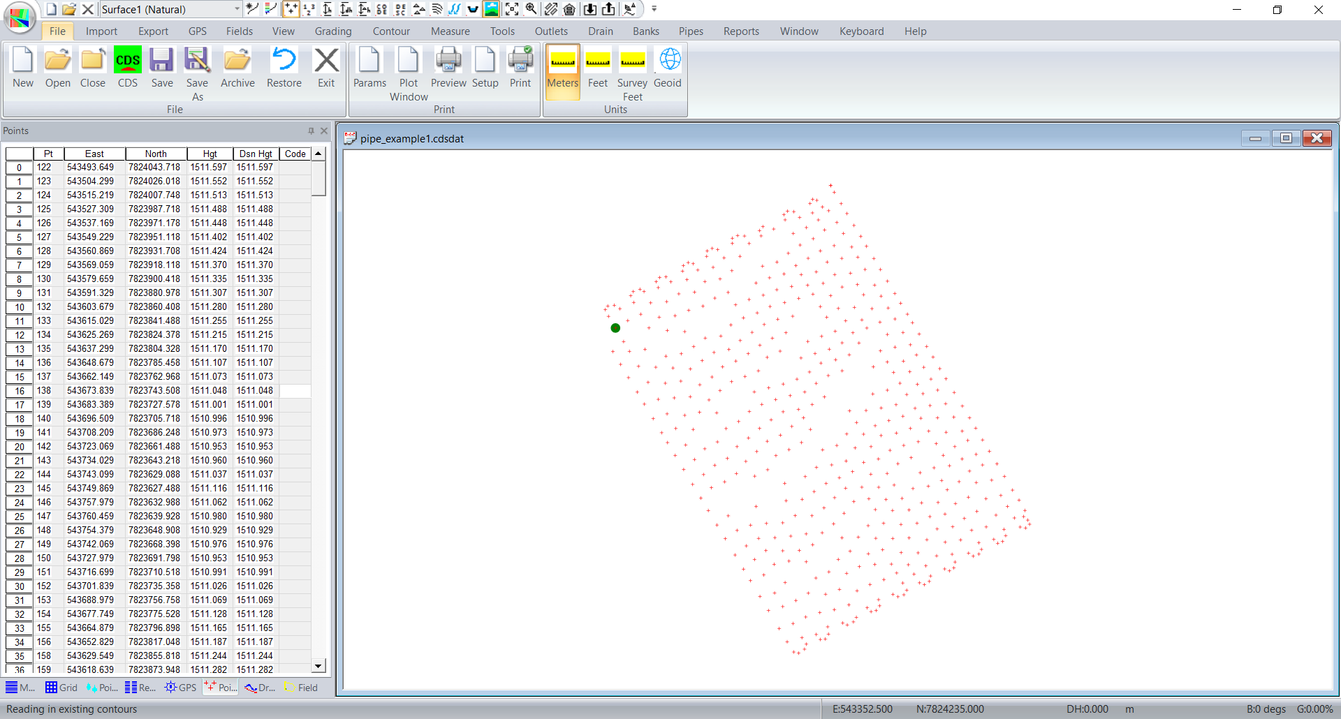
This data was picked up with a Trimble Field Level2 system. The green dot is a masterbench reference point.
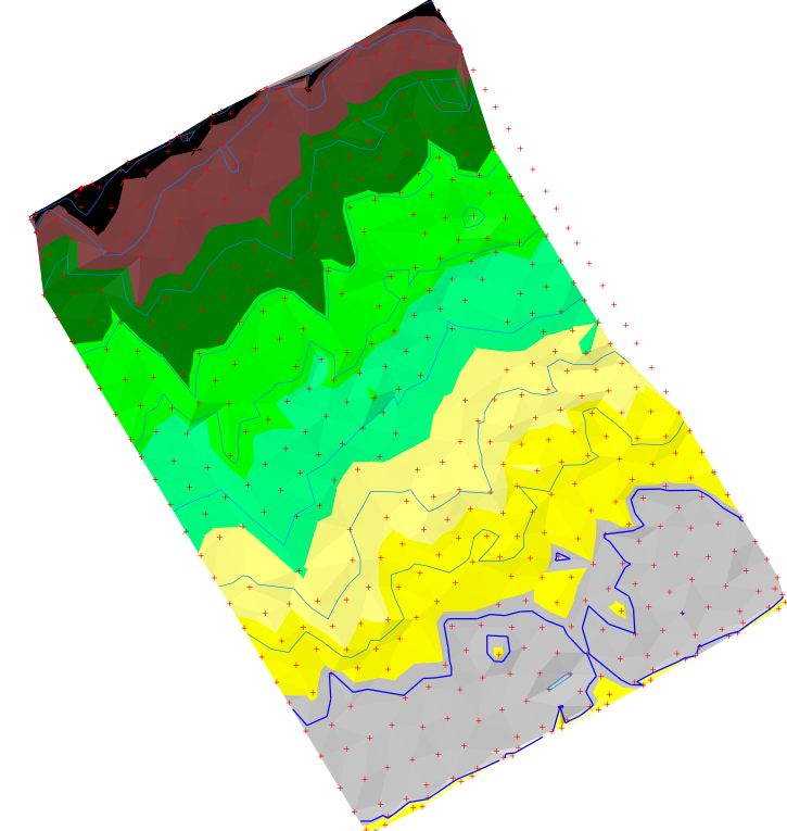
The first thing that we wish to do is to get a feel for where the water drains. Click on the Contour menu and click on "Auto Create". Triangles and Contours are formed. If you wish to display the contours now click on the View menu and click on "Contours" for them to be displayed. You can adjust the contour interval from the Contour -> Surface Parameters -> Minor Contour Interval value if need be. I changed the minor interval to 0.1 meters.
We also have the option of coloring in by height. Under the Contour -> Surface colors you can enter the appropriate heights and specify the color to be used.
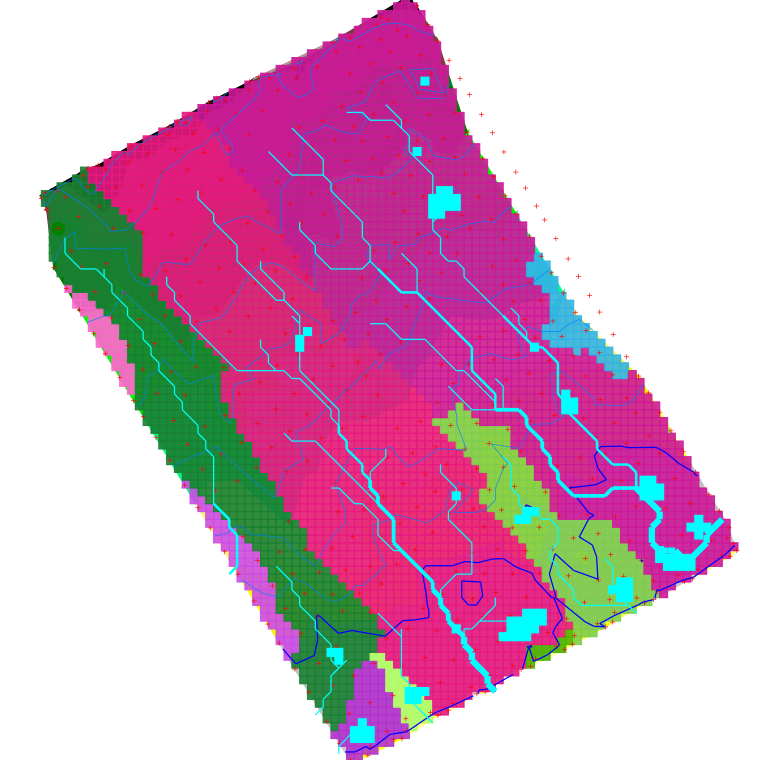
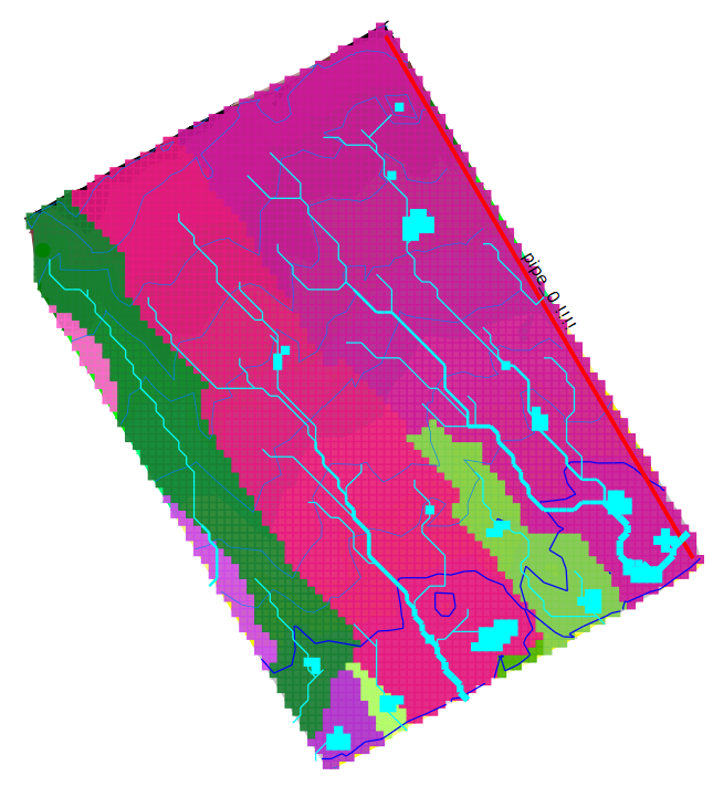
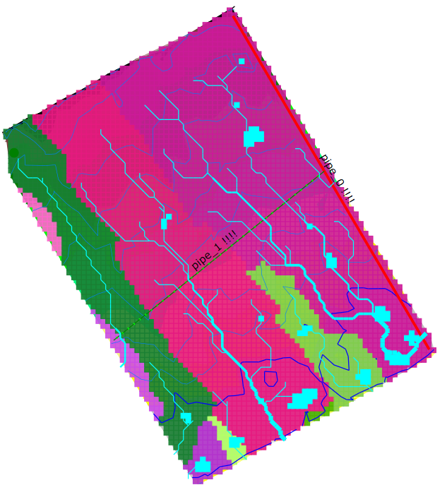
Under the View menu we also have the option to display tributaries and also catchment areas. We have the three different views shown below.
The right most view showing tributaries as well as the catchment areas shows that we have a slight ridge across the middle of the field as well as another ridge on the western side. On the Eastern side we can see the tributary has a major branch a quarter of the way up from the southern border. Please note the catchment routine works on where the water exists the edge of the job. It doesn't differentiate additional sub-catchments inside the job.
We now need to design the pipe layout. The designer now needs to decide whether they are going to drain each catchment or the larger catchments seperately or are we going to minimize the number of mains / submains and make the laterals longer. Alternatively we could bend the laterals to follow the contours so that we can better minimize the depth of the pipe. There are pros and cons for each of the approachs. Do we minimize the number of laterals and make them longer. Is is a hassle to put in bendy lines for the laterals or is it easier for the operator to cut in straight lines.
When I look at this job I can see that the catchment areas across the job are fairly shallow. In this case I will initially design laterals that run across the job at the expense of areas that are going to lead to greater minimum depths. To this end I am going to click in a Main pipe running alongside the Eastern edge and run the laterals in that run across the field.
Click on Pipes -> Insert Main. Left click at the pipe outlet and left click in the segments. Once finished hit the Enter key. We now have a Main Pipe clicked in as follows. Next I will click in a lateral. I will click this in the middle of the job. I have specifically avoided the lateral at the bottom as the contours acroos the job drop towards the East except at the bottom.
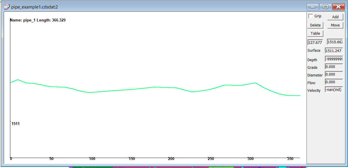
To click in the Lateral left click somewhere along the main pipe. In this case I will make the Lateral straight across the job. I have tried to follow the contour across in this first case. Once clicked in we want to view the profile. Under the Pipes menu click on Profile to get an idea of how the natural surface falls.
The outlet is at the left and in this case you can see that the surface height is dropping as we go towards the start of the lateral. This is the wrong way around. In this case we should be moving the start of the lateral northwards to flatten it out. In pipe design we normally have a range of grades that we are confortable with. Lets use the minimum grade that we can accept and that is 0.03%. If you click on the Measure -> Length Grade option. Left click at the outlet of the lateral and move the measure tool around until you see the point at a grade of 0.03%.
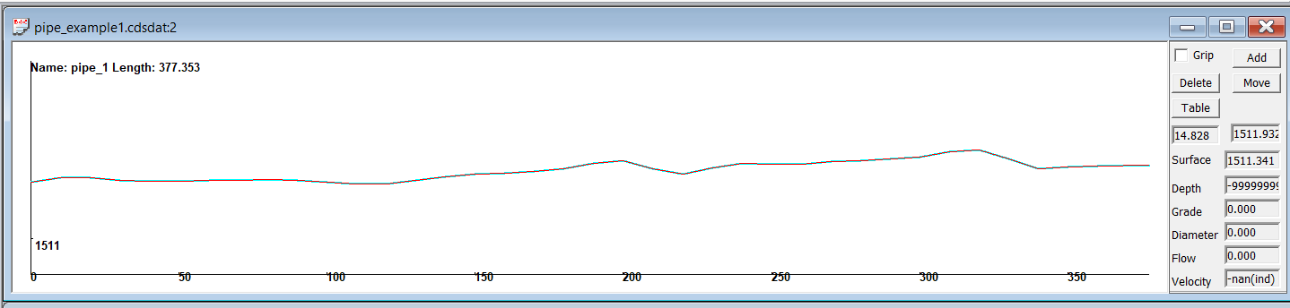
In this case we have the following and you can see the natural surface is rising across the job.
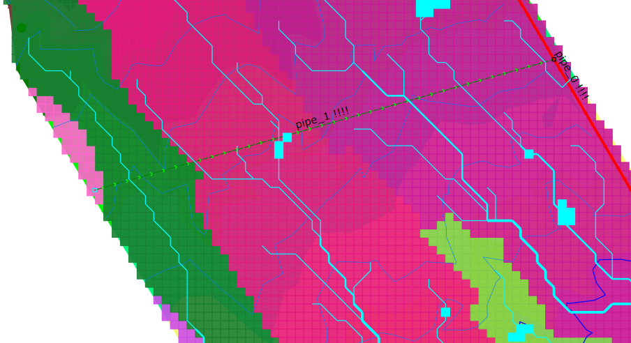
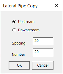
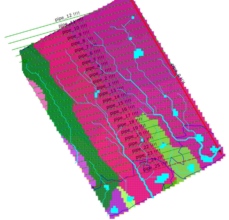
We are happy with this profile design. We now wish to copy this lateral along the main pipe. Make sure the lateral is selected. Now click on the Pipe -> Copy option. In this case we want the pipes 20 meters apart. Again this value comes down to experience, soil type, rainfall intensity or what we always use. Guess a number to use. If we go past the start of the main pipe it stops anyway. Repeat the copy command and put in some laterals downstream.
After this we have an area at the bottom that is not covered. I wouold change the most bottom Lateral into a SubMain. If you have a profile displayed and you left click on a pipe then the drain parameters are shown at the left. Select the SubMain option where it is shown as a Lateral.
Now add in a new Lateral near the SubMain outlet. Do a copy on this to fill in this area. I have also added in manually another Lateral Pipe along the bottom.
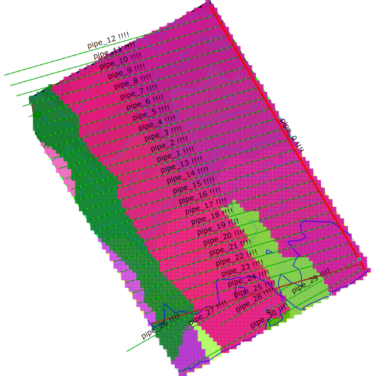
We now have the general layout as we want. However you will notice that some of the pipes extend past the edge while others don't make the edge. To fix this we can use the Trim command. You first need to select the pipes to be trimmed. Click on the Pipes -> Select command and draw a line that intersects through the relevant pipes. They will be draw as a dashed line. Now click on Trim and draw a line that differentiates the area.
We will try out this layout and see how we go. I guess at this stage we can turn-off the catchment area. Click on View -> Catchment to unshow.
At this stage we let Ezigrade calculate the best fit designs for each of these pipes. The algorithm uses Linear Programming which guarantees that we get an optimum solution for the constraints sent. However the design is only as good as the layout and the constraints set.
Click on Pipes -> Recalculate All.
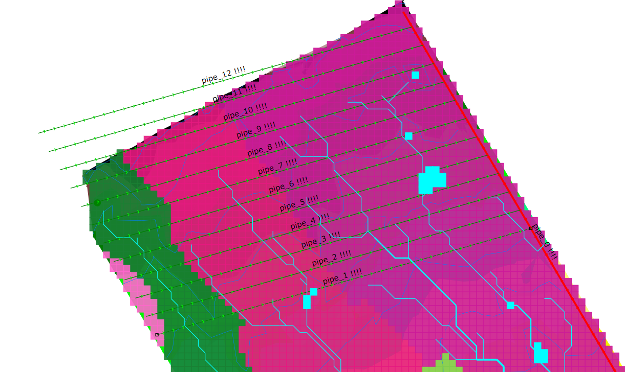
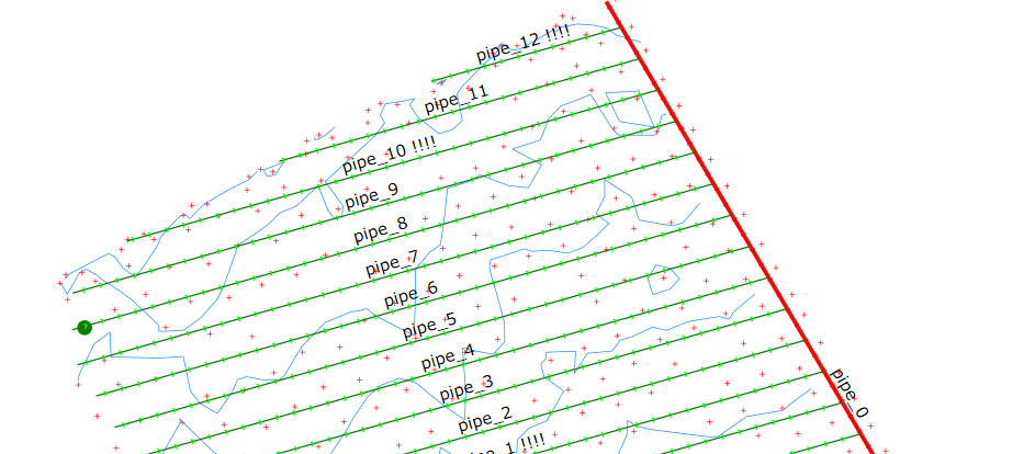
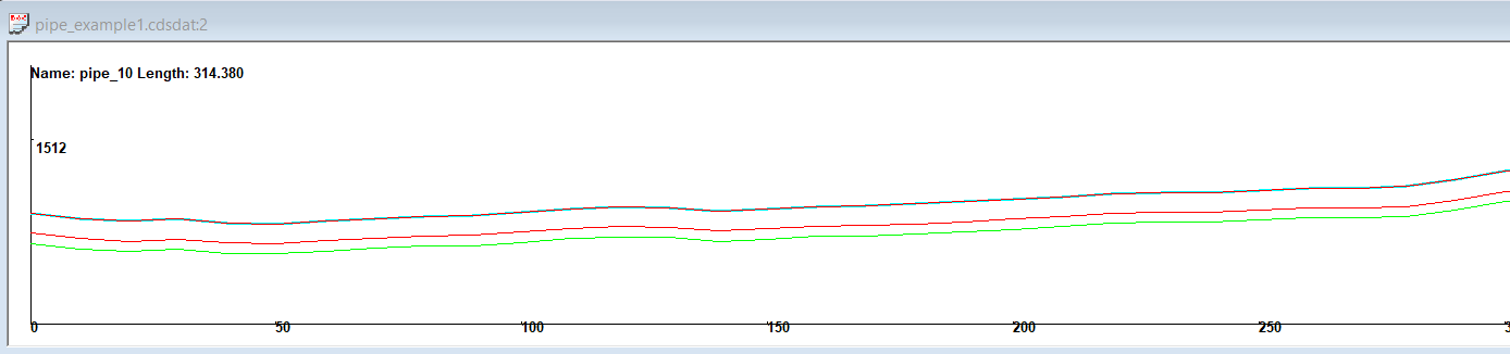
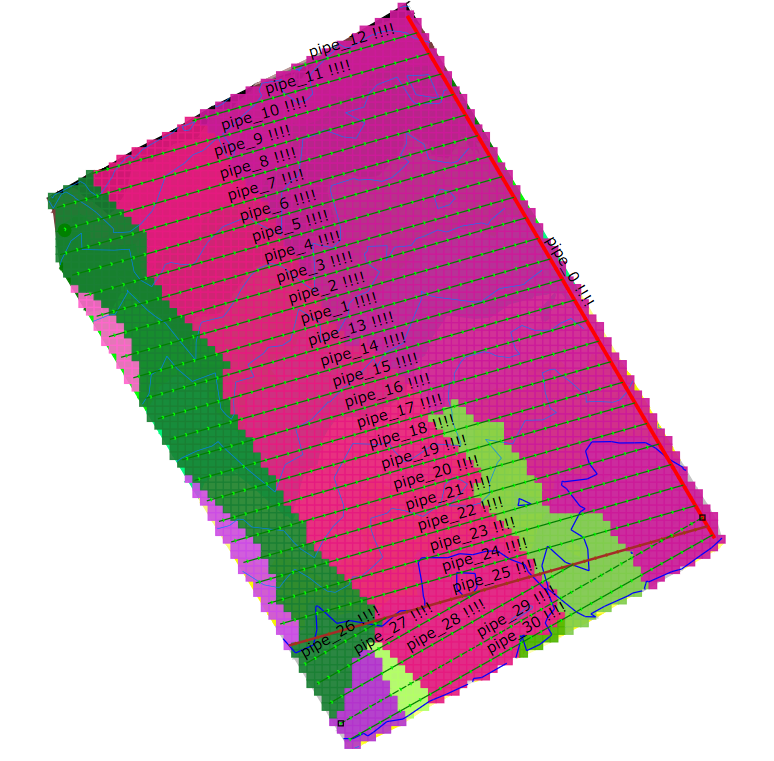
Ezigrade runs through each pipe and creates the optimum design. Pipes that are impossible to design within the constraints set are shown with the name and appended with !!!!. Make sure that you have the pipe names displayed. Look at the Pipes -> Params and Display name is set. In this case we have selected pipe_10 !!!!
In this case we can see that the natural surface around the outlet of this pipe rises a bit. So the point on the main pipe is too high so that we can't maintain a minimum grade and join into the Main. Either we can relax the constraints on the main pipe of reduce the minimum depth along this lateral. You as the designer needs to decide what you want to do.
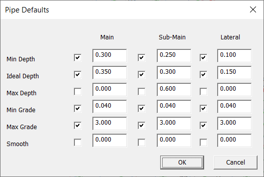
As I have a few laterals that fail I tried dropping the preferred height of the Main from 350mm to 400mm. This fixed all the issues. It may be worthwhile tweaking this value some more to reduce the height if you wish.
So we know have all the pipes with a profile design and they are within the constraints specified. An experienced operator may know by feel what pipe sizes are expected to be used here. If that is the case then you can export the designs to your pipe laying machinary and enact your design.
Sizing the Pipe Work
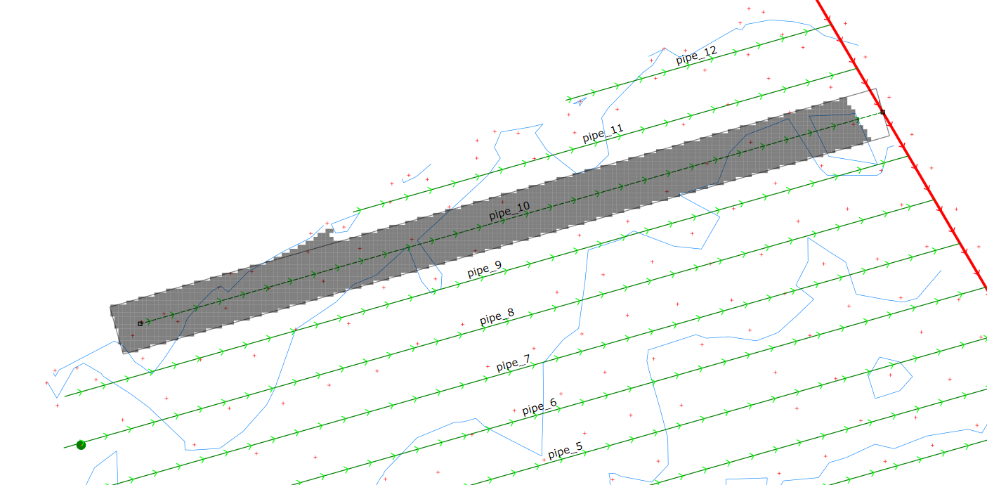
Before we can calculate pipe sizes we need to calculate the catchment area of each pipe. This is calculated based on a corridor around the pipe plus any water that flows into this area. Click on Pipes -> Catchment. Ezigrade goes away and calculates the catchment area for each Pipe. Once this is done then click on a pipe to check the area it is picking up. The screen shot on the left shows the area related tp pipe_10 while the screen shot on the right shows the catchment area of the main. It includes any submains and laterals that are ultimately connected to it.
Once we have this we can calculate the pipe diameters. Click on Pipe -> Calc Diameter
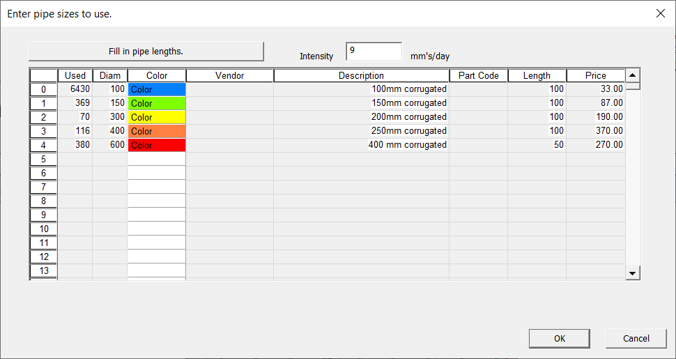
These pipe sizes presented are theoretical values based on our assumed rainfall intensity. We now wish to set the pipes to actual pipe diameters that we can purchase.
Bring up the the Pipes -> Pipes table. Fill it in as appropriate. If you know prices etc fill them and you will be able to create a costings quote later. Click on the "Fill in Pipe Lengths". Ezigrade will calculate practical pipe diameters.
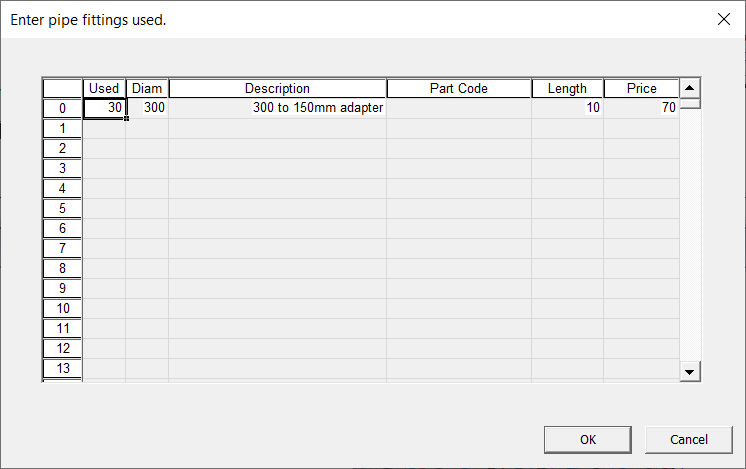
You can also fill in the Pipes -> Fittings table. This is a manual process. Again include costings etc for an included quote.
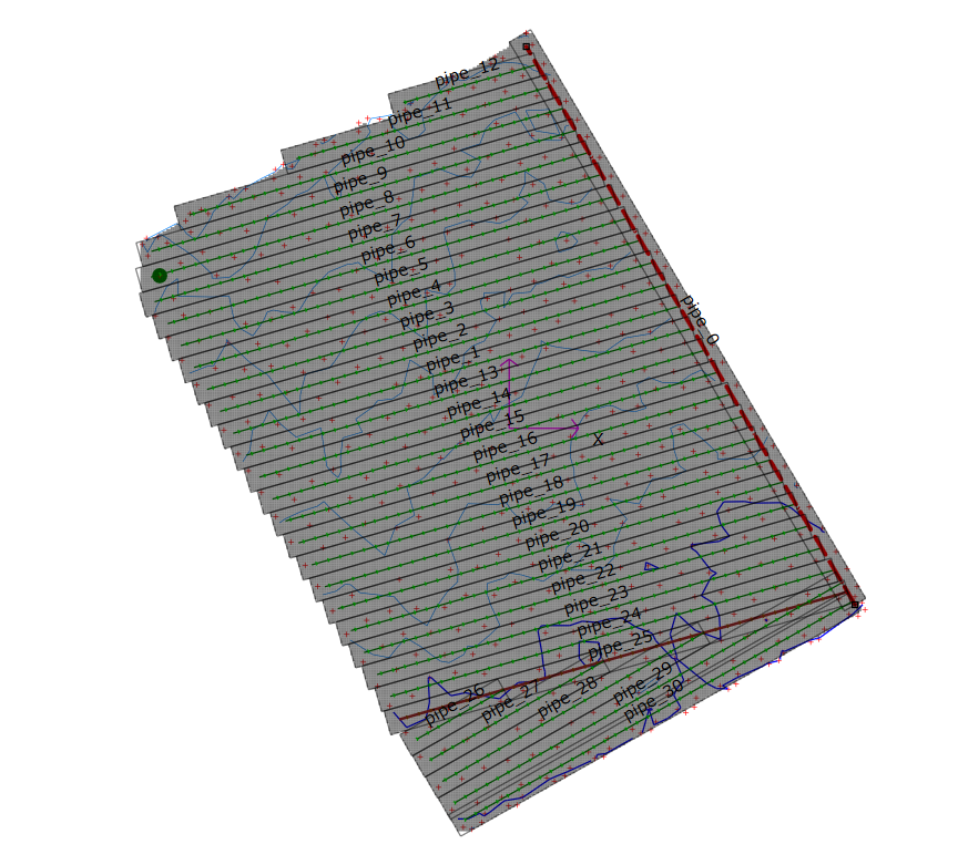
Once the pipe diameters have been calculated have another look at the plan view. Make sure you turn on the pipe diameters table. This is found in Pipes -> Params dialog.
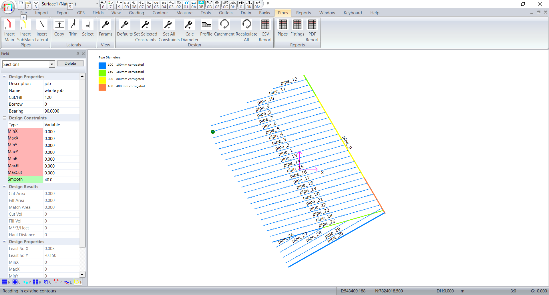
Again make sure this all makes sense.
We are now in a position to create a report to present to our client. Click on Pipes -> PDF Report. Our first page looks like this:
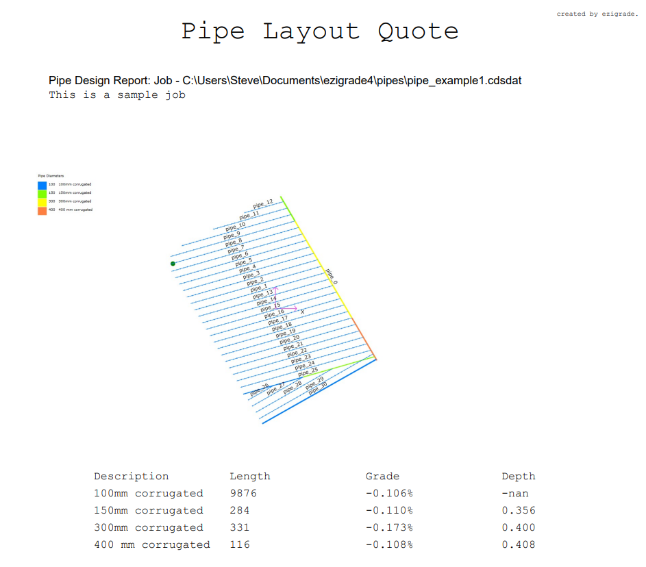
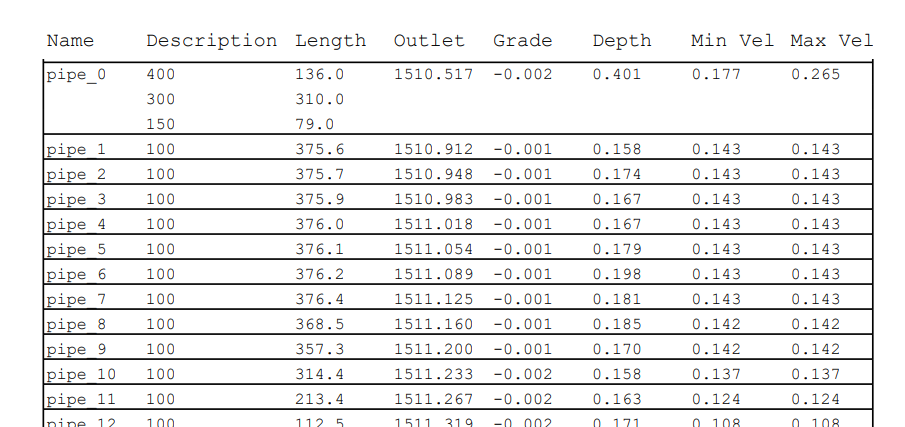
and the individual pipes are described:
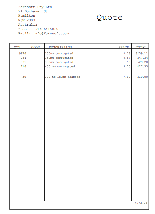
and we get a quote such as:
Make sure that the water velocities are within your allowable limits. We are still working on this module and intend to refine the product further as we go along.
|