| < Previous page | Next page > |
Designing a Drain - then Drainage Network
In this example we are first going to design a simple drain and merge into a new design surface. We are then going to explain how we can join and merge drains together to create a network of drains or waterways.
Simple Drain Design:
In this example we are going to create a simple drainage design and explain the process and options that we have. The first stage is obviously to obtain some data that we can work on. Ezigrade contains routines to import data in a number of different formats. There is also the ability to pick up data directly from RTK GPS systems.
We have the following rather small job that we wish to add a drainage channel to. You would probably be looking at a larger area but the process is the same no matter how large or small the area is.
I would also note: the Ezigrade drainage routines are a subset of the routines available in CDS. In Ezigrade we are trying to simplify and streamline routines that are most often used by framing contractors. It is possible that the Ezigrade routines can not design the scenario you are after. In that case you can fall back on the CDS routines.
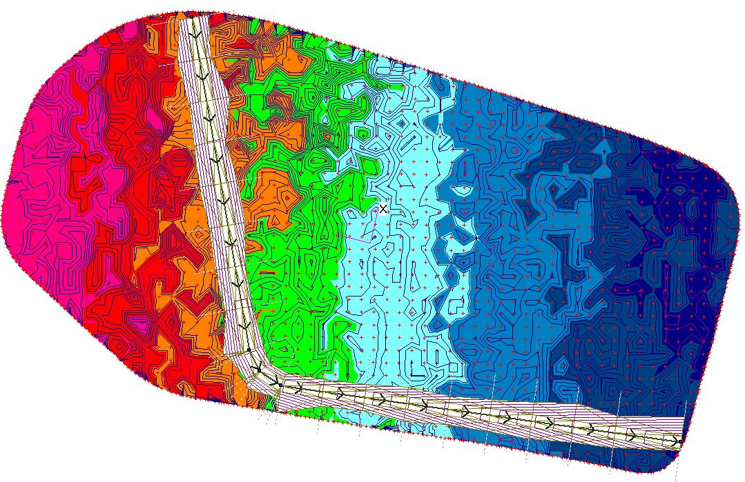
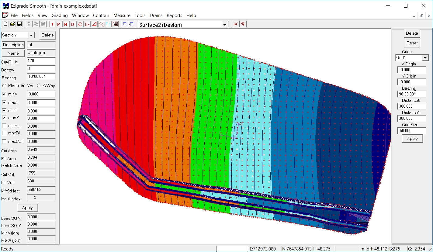
The job looks as follows:
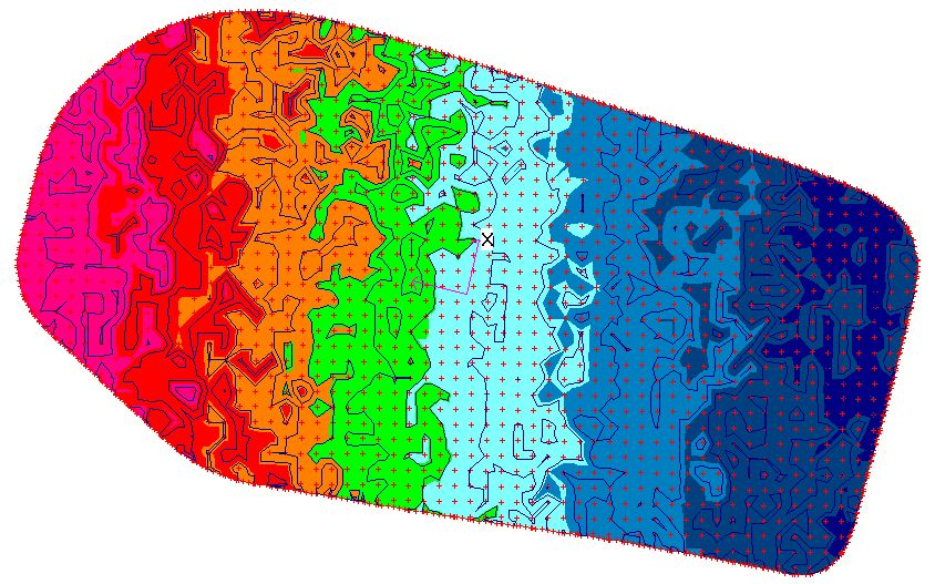
The high point is on the left of the screen and water generally flows to the East. The surface has not been graded and contains various ponds and irregularities. In this example we wish to merge the drain into the existing surface and create a new design surface containing this drain. There are also options to merge in the drain to a new graded surface.
Our first job is to draw in a center line for the new drain. We are going to cut across the field from north to south and then bend the drain so it flows east along the bottom border. Use the Drain -> Insert Drain menu item. Once we click on this item; we firstly left click on the screen and release. Now move the mouse and a line is draw. Left click again to finish this line and keep moving to draw the next line segment. Draw in our outline and when finished, hit the enter key. If you make a mistake; hit the escape key and you can start again.
We end up with the following:
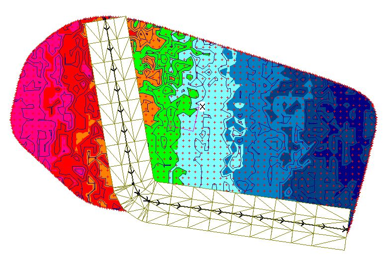
We initially are shown the new drainage corridor. At present we haven't defined a profile for the design or how the sections are displayed. Hence no design contours etc can presently be displayed.
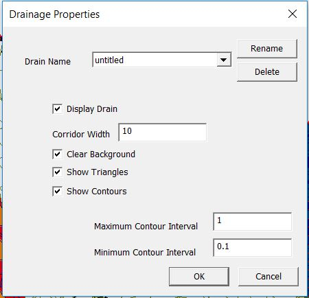
The width of the corridor and whether we display triangles and contours in the drainage corridor is usable definable. Click on Drain -> Properties menu item. In this example we have shrunk the default width.
To complete a design we first need a vertical alignment of the drain centre line and also specify how the section is to be displayed.
Click on the "Drains - Design Profile" option. We are presented with the natural surface. We can then click in the new design profile. As we are designing a ring tank the height is a constant value. If you look at the screen shot below. You can see the existing natural surface. The design is clicked in at the top; using the Add, Delete and Move buttons. You also can take note of the design height shown when you move the mouse.
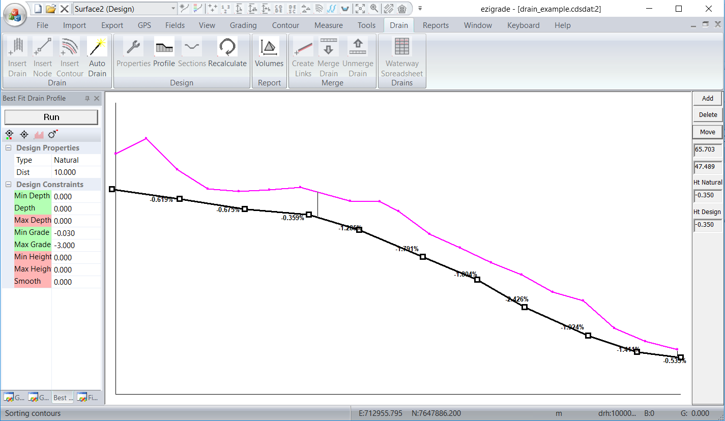
Once you are happy with your vertical design then click on the "x" top right to close down the profile view. The profile is saved.
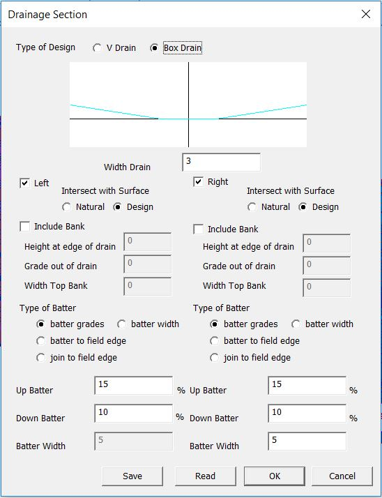
The next stage is to define how we want the section to be displayed. Click on the "Drains - Design Section" and you are presented with the following dialog. If you look at the dialog you can see that it is in sections. Initially we need to define whether we have a flat bottom or a V bottom. In this case we are defining a box drain so bottom of drain is flat. For this case we need to specify a width. This is not used for a V drain.
We can display either or both sides of the drain. We can also specify whether we intersect with the natural or the design surface. In this case we are going to specify the "design" option.
We can also include an optional Bank either or both sides.
Lastly we specify how the section merges into the surface. We can define batter grades or width or join to existing field edges. In this case we are simply grading to the surface. When happy click OK.
In this case we have specified that we are grading to the design surface. However we only have a natural surface so far. We now wish to create a design surface that incorporates this design. Firstly click on the "Tools - Copy Natural Heights to Design" menu item. This sets all the points so that there design height is the same as the natural height.
If you now click on the Drains -> Recalculate icon we have the following:
The drain design with contours is now shown. At present it is a distinct entity to either the natural or design surface.
We want to add in our design to the existing design surface. Now click on the "Designs - Merge Drains to Design" and the drain/bank is added to the design surface. Initially you won't see anything as the drain is still shown. Click on the drain view icon to turn off the drain display.
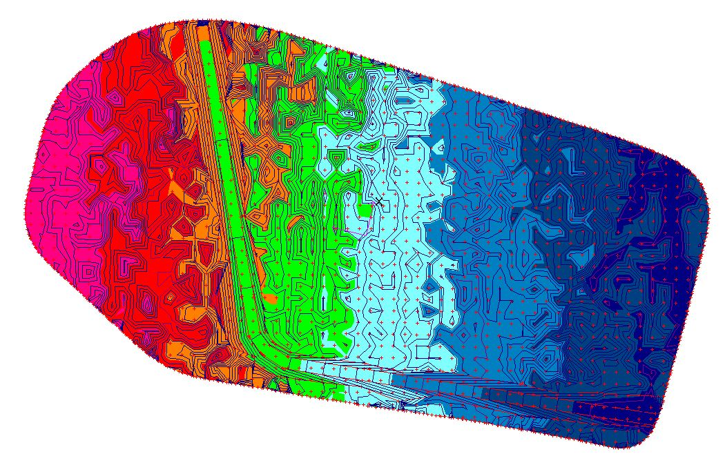
We now have the following new design which shows our completed design:
You can now display a volume report or export our design to our tractor to create it in the field. Please see the "Designing a Ring Tank" which expands on these subjects.
Modifying the Sections along the Drain:
We can now modify the sections as we go along the drain. The Section Dialog a few pictures back allows you to design the section across the drain that is repeated along its left. Towards the bottom of the dialog you will notice that there is an option for "Read" and "Save". Clicking the "Save" button stores the section as designed into an internal file structure. "Read" brings in an existing file structure. The procedure to have different sections along a drain is to:
We have a Dialog where this is specified. From the Drain menu click on "Drainage Spreadsheet". If you never open this option then the drain is created with the default section as always. The current drain is shown in a grid. On the right you can specify the section/reach name. You need to enter in the name of the section/reach as it was saved from the section dialog. You don't need to specify a reach at every line. The software simply keeps using a previously defined line until we get to a different one. The following screen shot shows an example:
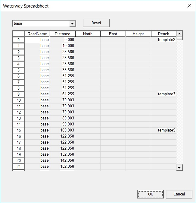
In this case we have defined three sections. In these templates we simply changed the width of the internal box drain to increase capacity. To make sense the same type of section should be used along the drain. For example it doesn't make sense to change from a V drain to a Box drain with banks. The drain should now display with the different sections. To create below we simply merged the design. Please not how the drain increases in capacity as we go along the drain.
 Creating a Drainage Network:
Ezigrade allows you to create multiple drains in the same job. For more than one drain it is important that each section drain has a unique name. When a drain is entered. You can left click on the drain to select it. Then click on "drain properties" from the drainage menu and enter a unique drain name.
If the drains are independent of each other then there is no conceptual change from having one drain. Simply first click on a drain first to select it. Then operate on the drain.
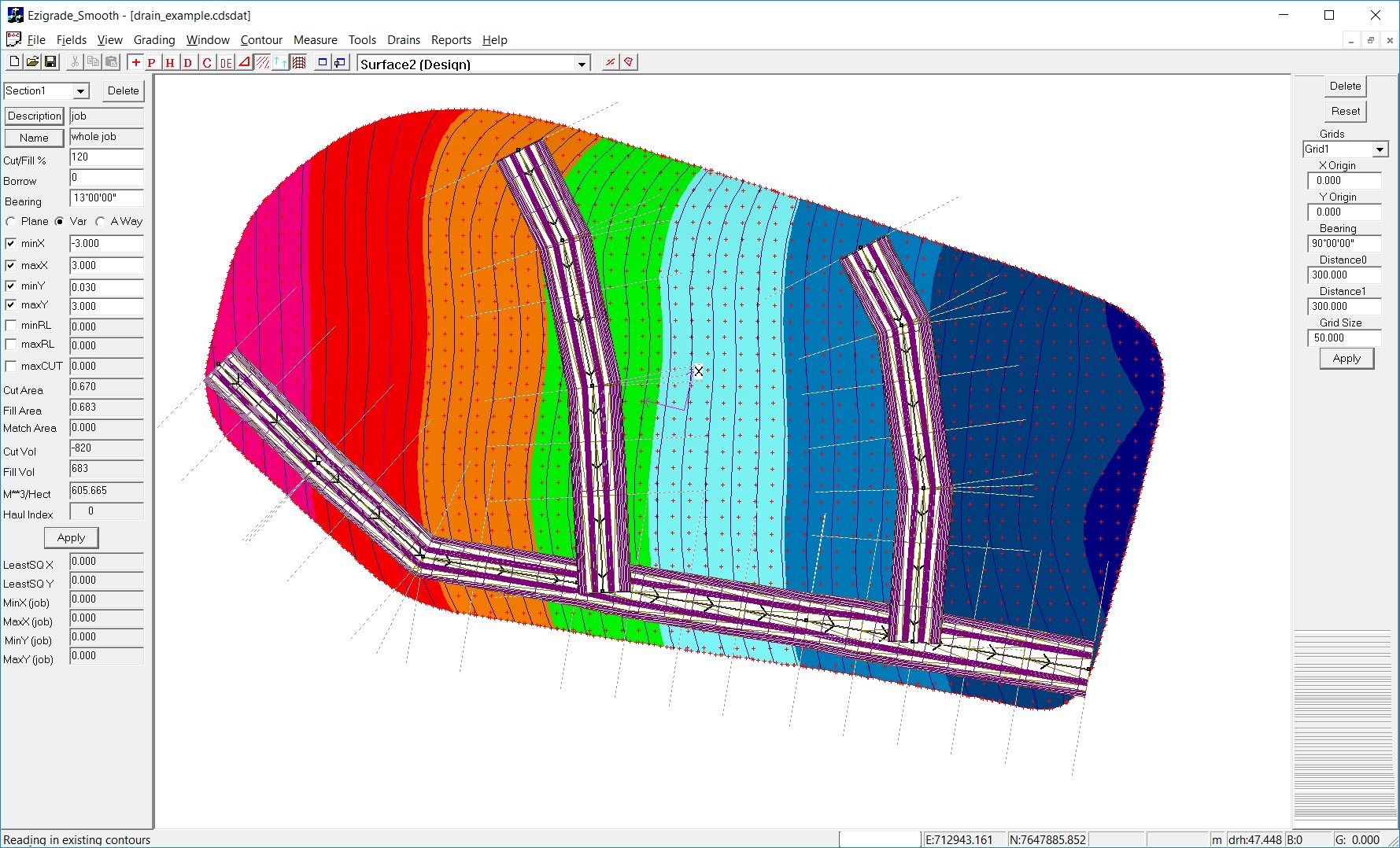
It gets more complicated when we wish to join drains together. Well more complicated for the software; hopefully not for the user. In the example shown we have our main drain as shown. We are going to create two more drains that flow into this main one. As before enter in your respective drains. Design the main/base drain first so it is at the bottom. They are displayed on the screen in the order they are entered. Design in your secondary drains and if necessary tertiary drains. Here we have a main drain and two side drains:
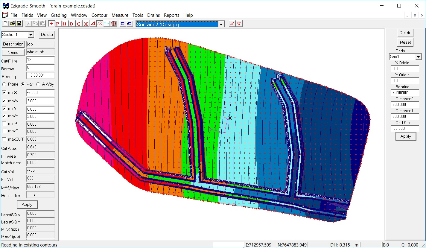
At present the individual drains are still drawn separately. To add the drains into the job you need to make sure you put in the Base drain first. In this example merge the base drain into the job as always. Now merge the side drains. There order doesn't matter. The software automatically creates the proper breaklines at the intersection's. After merging the design surface looks like:
If you need to make changes then you can unmerge the drain. At present you will need to unmerge all the intertwined drains; make the changes and merge back in.
|